Magnetic Flow Meter Working Principle
Magnetic Flow Meter Working Principle
In the realm of industrial process control, the accurate measurement of liquid flow is essential for maintaining efficiency, safety, and product quality. Among the various technologies available, the electromagnetic flow meter, commonly referred to as a magmeter, stands out for its ability to measure the flow of conductive liquids without obstructing the flow path. This article provides an in-depth exploration of the magnetic flow meter working principle, its technical components, selection criteria, and practical installation guidelines.
As a professional manufacturer of industrial measurement instruments, Welk provides a range of solutions tailored to demanding environments. Understanding the underlying physics of these devices is the first step in selecting the right equipment for water treatment, chemical processing, or industrial automation. For a comprehensive overview of available technologies, engineers often consult the Main Page of specialized instrument providers to compare specifications.
The Fundamental Principle: Faraday’s Law
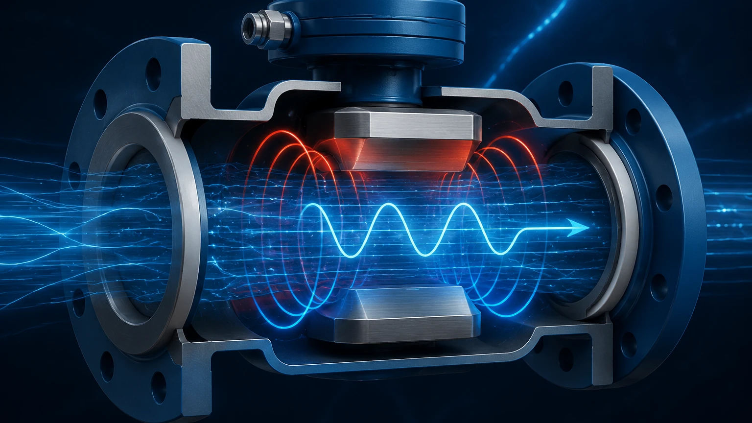
The magnetic flow meter working principle is based on Faraday’s Law of Electromagnetic Induction, first formulated by Michael Faraday in 1831. The law states that a voltage is induced when a conductor moves through a magnetic field. In the context of a flow meter, the "conductor" is the process fluid itself.
The Mathematical Equation
The relationship between the induced voltage and the fluid velocity is expressed by the following equation:
E = k · B · D · V
Where:
* E is the induced voltage (signal) generated in the fluid.
* k is a constant specific to the instrument (meter constant).
* B is the magnetic field strength produced by the coils.
* D is the inner diameter of the flow tube (the distance between the electrodes).
* V is the average velocity of the conductive fluid.
Because the magnetic field strength (B) and the pipe diameter (D) are kept constant by the meter's design, the induced voltage (E) is directly proportional to the fluid velocity (V). By measuring this voltage, the transmitter can calculate the volumetric flow rate based on the cross-sectional area of the pipe.
The Role of Conductivity
For the magnetic flow meter working principle to function, the fluid must possess a minimum level of electrical conductivity. Most industrial magmeters require a conductivity of at least 5 μS/cm (microsiemens per centimeter). This makes the technology ideal for water, acids, bases, and slurries, but unsuitable for hydrocarbons, distilled water, or gases, which lack the necessary ions to conduct electricity and generate a measurable voltage.
Key Components of a Magnetic Flow Meter
A magmeter consists of two primary parts: the flow sensor (installed in the pipeline) and the transmitter (the electronic brain that processes the signal).
1. The Flow Tube and Liner
The flow tube is typically constructed from non-magnetic stainless steel to prevent interference with the magnetic field. Since the tube is metal, it must be lined with an insulating material to prevent the induced voltage from short-circuiting into the pipe wall. Common liner materials include PTFE (Teflon), Hard Rubber, and PFA.
2. Electromagnetic Coils
Two coils are positioned on opposite sides of the flow tube (usually at the top and bottom). When energized by the transmitter, these coils generate a uniform magnetic field that permeates the entire cross-section of the pipe.
3. Electrodes
A pair of electrodes is mounted flush with the pipe wall, positioned perpendicular to both the flow direction and the magnetic field. These electrodes "pick up" the induced voltage generated by the moving fluid and send it to the transmitter.
4. The Transmitter
The transmitter provides the excitation current to the coils and amplifies the minute voltage signal (often in the millivolt range) from the electrodes. It filters out noise, converts the signal into a flow rate, and provides outputs such as 4-20mA, pulse, or digital protocols (HART, Modbus).
Selection Criteria and Material Compatibility
Selecting the correct magmeter requires matching the instrument materials to the chemical and physical properties of the process fluid. The choice of liner and electrode material is critical for the longevity of the device.
Liner Selection Table
| Liner Material | Temperature Range | Characteristics | Common Applications |
| :— | :— | :— | :— |
| PTFE (Teflon) | -40°C to +180°C | Excellent chemical resistance, anti-adhesive. | Strong acids, alkalis, high-temp fluids. |
| Hard Rubber | 0°C to +80°C | Good abrasion resistance, cost-effective. | Water treatment, wastewater, low-temp slurries. |
| Polyurethane | -20°C to +60°C | Superior abrasion resistance. | Mining slurries, sand-laden water, pulp. |
| PFA | -40°C to +150°C | Similar to PTFE but better for vacuum conditions. | Chemical processing, pharmaceutical. |
Electrode Material Selection
* 316L Stainless Steel: Standard for water and mildly corrosive liquids.
* Hastelloy C: Used for aggressive chemicals and sea water.
* Titanium: Highly resistant to chlorides and chlorites.
* Tantalum: Excellent resistance to almost all acids except hydrofluoric acid.
* Platinum/Iridium: Used for the most extreme chemical environments.
Installation Considerations
To ensure the magnetic flow meter working principle is applied accurately, proper installation is paramount. Errors in mounting can lead to signal instability or significant measurement inaccuracies.
1. Straight Pipe Requirements
Flow profiles must be stable for accurate measurement. Typically, a straight run of 5 to 10 times the pipe diameter (5D–10D) is required upstream of the meter, and 2 to 5 times the diameter (2D–5D) is required downstream. This minimizes turbulence caused by valves, elbows, or pumps.
2. Pipe Orientation and Fullness
The magmeter must always be full of liquid. If the pipe is partially empty, the meter will over-read or fail to provide a stable signal.
* Vertical Installation: Flowing upwards is the preferred orientation, as it ensures the pipe remains full and prevents air bubbles from collecting at the electrodes.
* Horizontal Installation: The electrodes should be positioned on a horizontal plane (3 o'clock and 9 o'clock positions). If they are at the top and bottom, air bubbles or sediment may cover them, causing signal loss.
3. Grounding
Since the induced voltage signal is very small, it is highly susceptible to electrical noise. Proper grounding is essential. The fluid, the sensor, and the transmitter must be at the same electrical potential. If the pipeline is made of non-conductive material (like PVC), grounding rings must be used to provide an electrical path to the fluid.
Advantages and Limitations
Advantages
* No Pressure Drop: Because there are no obstructions in the flow path, there is no additional pressure loss in the system.
* No Moving Parts: This leads to high reliability and minimal maintenance compared to mechanical meters.
* Bi-directional Measurement: Magmeters can measure flow in both forward and reverse directions.
* High Accuracy: Modern magmeters can achieve accuracies of ±0.2% to ±0.5% of the flow rate.
* Handles Slurries: The unobstructed bore is ideal for liquids with high solid content.
Limitations
* Conductivity Requirement: Cannot measure oils, steam, or gases.
* Temperature and Pressure: Limited by the physical properties of the liner and electrode seals.
* Cost: Generally more expensive than basic mechanical meters for large pipe sizes.
Maintenance and Troubleshooting
While magmeters are low-maintenance, certain issues can arise over time.
* Electrode Coating: In applications involving fats, oils, or sticky substances, a layer can build up on the electrodes, insulating them from the fluid. Some meters feature "electrode cleaning" circuits or removable electrodes to address this.
* Liner Wear: In abrasive slurry applications, the liner may eventually wear down, leading to leaks or sensor failure. Regular inspection of the liner integrity is recommended during plant shutdowns.
* Signal Noise: If readings are erratic, check for nearby VFDs (Variable Frequency Drives) or large motors that might be inducing interference. Ensure grounding connections are secure and corrosion-free.
Frequently Asked Questions (FAQs)
Q: Can a magnetic flow meter measure the flow of deionized water?
A: Generally, no. Deionized or distilled water has very low conductivity (often below 1 μS/cm), which is insufficient for the magnetic flow meter working principle to generate a detectable voltage.
Q: What happens if there are air bubbles in the liquid?
A: Small amounts of entrained air may cause slight inaccuracies, but large slugs of air can cause the signal to fluctuate wildly or cause the meter to report an "empty pipe" error.
Q: Does the viscosity of the fluid affect the accuracy?
A: No. One of the major benefits of magmeters is that they are independent of fluid viscosity, density, and temperature, provided the fluid remains conductive and the flow is sub-sonic.
Q: How often should a magnetic flow meter be calibrated?
A: For most industrial applications, a factory calibration is sufficient for several years. However, in regulated industries like food and beverage or pharmaceuticals, annual or bi-annual wet calibrations may be required.
For engineers seeking reliable instrumentation, Welk offers a diverse portfolio of measurement devices. Whether you require radar level meters for tank monitoring or electromagnetic meters for flow control, visiting the Main Page provides access to technical specifications and application support necessary for successful project execution.
By adhering to the principles of Faraday's Law and ensuring meticulous installation and material selection, magnetic flow meters provide one of the most robust and accurate methods for liquid flow measurement in modern industry.