Magnetic Flow Meters
Magnetic Flow Meters
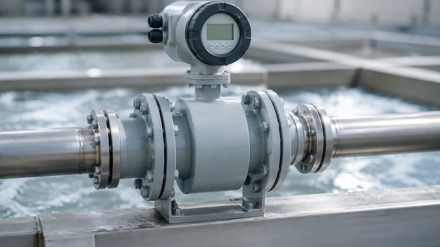
Magnetic flow meters, often referred to as magmeters, represent one of the most versatile and accurate technologies for measuring the volumetric flow rate of conductive liquids. In industrial process control, where precision and reliability are paramount, these instruments have become a standard choice for applications ranging from water treatment to chemical processing. Unlike mechanical flow meters that rely on moving parts, magnetic flow meters utilize electromagnetic principles, offering a maintenance-free solution that does not obstruct the flow path or cause pressure drops.
Understanding the engineering principles behind these devices is essential for any technical professional tasked with system design or procurement. While many industrial facilities focus heavily on tank inventory management through advanced level measurement, integrating accurate flow data is critical for mass balance, dosing accuracy, and overall process efficiency. For those seeking comprehensive instrumentation solutions, including the level sensors that often work in tandem with flow systems, visiting the Main Page of a professional manufacturer provides a broader perspective on integrated process automation.
Fundamentals of Electromagnetic Flow Measurement
The operation of magnetic flow meters is based on Faraday’s Law of Electromagnetic Induction. This principle states that a voltage is induced when a conductive medium passes through a magnetic field. In the context of a flow meter, the liquid itself acts as the conductor.
The Measurement Principle
When a conductive liquid flows through a pipe of diameter ($D$) at a velocity ($v$), and is subjected to a magnetic field of density ($B$) generated by electromagnetic coils, an electromotive force ($E$) is produced. This relationship is mathematically expressed as:
$$E = k \cdot B \cdot v \cdot D$$
Where:
* E is the induced voltage (signal).
* k is a constant specific to the instrument.
* B is the magnetic field strength.
* v is the average velocity of the liquid.
* D is the pipe diameter (distance between electrodes).
Because the magnetic field strength and the pipe diameter are constant, the induced voltage is directly proportional to the flow velocity. This voltage is picked up by two electrodes mounted on opposite sides of the pipe wall and is then processed by a transmitter to provide a flow rate reading, typically in cubic meters per hour ($m^3/h$) or liters per second ($L/s$).
Conductivity Requirements
A critical prerequisite for using magnetic flow meters is that the fluid must be electrically conductive. Most industrial magmeters require a minimum conductivity of 5 microsiemens per centimeter ($μS/cm$). This makes them ideal for water, acids, bases, and slurries, but renders them unsuitable for hydrocarbons, distilled water, or gases, which lack sufficient conductivity to induce a measurable voltage.
Selecting the Right Magnetic Flow Meter for Industrial Applications
Choosing the correct magnetic flow meter involves more than simply matching the pipe size. Engineers must evaluate the chemical compatibility of the wetted parts, the process temperature, and the physical properties of the fluid.
Liner Material Selection
Since the meter body is usually metallic (often stainless steel), the interior must be lined with an insulating material to prevent the induced voltage from short-circuiting through the pipe wall. The choice of liner depends on the temperature and abrasiveness of the medium.
| Liner Material | Temperature Range | Common Applications |
| :— | :— | :— |
| PTFE (Teflon) | -20°C to +180°C | Highly corrosive chemicals, strong acids, and bases. |
| Hard Rubber | 0°C to +80°C | General water treatment, wastewater, and non-corrosive fluids. |
| Neoprene | -20°C to +60°C | Abrasive slurries, mining, and pulp and paper industries. |
| PFA | -20°C to +150°C | High-purity applications, food and beverage, and pharmaceutical. |
| Polyurethane | -20°C to +50°C | Extremely abrasive media with high solid content. |
Electrode Material Selection
The electrodes are the only other component in direct contact with the process fluid. They must resist corrosion and chemical attack to ensure a stable signal.
* 316L Stainless Steel: The standard for water and mildly corrosive liquids.
* Hastelloy C: Used for seawater, salt solutions, and oxidizing acids.
* Titanium: Ideal for chlorides and hypochlorites.
* Tantalum: Highly resistant to almost all acids, including hydrochloric and sulfuric acid.
* Platinum/Iridium: Reserved for the most aggressive chemical environments due to its high cost.
Critical Installation Guidelines for Accuracy
The accuracy of magnetic flow meters is highly dependent on the flow profile of the liquid. For the meter to provide a reliable reading, the velocity distribution across the pipe cross-section must be symmetrical.
Straight Pipe Run Requirements
To ensure a stable flow profile, magmeters should be installed with a specific length of straight pipe before and after the sensor. While modern digital signal processing has reduced these requirements, the following "Rule of Thumb" remains the industry standard:
1. Upstream (Inlet): Minimum of 5 times the nominal pipe diameter (5D).
2. Downstream (Outlet): Minimum of 2 times the nominal pipe diameter (2D).
If the installation site involves high-turbulence elements like partially open valves or multiple elbows in different planes, the upstream requirement may increase to 10D or more.
Orientation and Filling
A magnetic flow meter must always be full of liquid to function correctly. If the pipe is only partially full, the meter will either read inaccurately or fail entirely.
* Vertical Installation: The preferred orientation is vertical with the flow moving upward. This ensures the pipe remains full and prevents the entrapment of air bubbles at the electrodes.
* Horizontal Installation: If installed horizontally, the electrodes must be positioned on the horizontal plane (3 o'clock and 9 o'clock positions). This prevents air bubbles at the top or sediment at the bottom from interfering with the electrode signal.
* U-Shaped Piping: In gravity-fed systems, installing the meter in a "sump" or U-shaped section of the pipe ensures it remains flooded even when the flow stops.
Grounding
Because the induced voltage signal is very small (often in the millivolt range), it is susceptible to electrical noise. Proper grounding is non-negotiable. If the pipeline is made of plastic or is lined with an insulating material, grounding rings must be installed to provide a reference point for the fluid potential and to divert stray currents away from the electrodes.
Limitations and Operational Risks
While magnetic flow meters are robust, they are not universal solutions. Engineers must be aware of specific limitations to avoid measurement errors or equipment failure.
1. Non-Conductive Fluids: As mentioned, magmeters cannot measure oils, greases, or pure alcohols. If the conductivity drops below the threshold (e.g., in ultra-pure water systems), the signal will be lost.
2. Vacuum Conditions: Some liners, particularly PTFE, can collapse or peel away from the pipe wall if the system experiences a vacuum. In applications where vacuum conditions are possible, PFA liners with mechanical reinforcement (such as a stainless steel mesh) should be specified.
3. Coating and Scaling: If the process fluid contains fats, oils, or minerals that can coat the electrodes, the meter may eventually fail to detect the induced voltage. In such cases, meters equipped with electrode cleaning circuits or removable electrodes are necessary.
4. Flow Velocity Limits: Magmeters generally perform best at velocities between 0.5 m/s and 10 m/s. At very low velocities, the signal-to-noise ratio becomes poor, leading to inaccuracy. At extremely high velocities, the liner may suffer from accelerated wear.
Integrating Flow and Level Measurement Systems
In many industrial scenarios, magnetic flow meters are used in conjunction with level measurement instruments to provide a complete picture of process dynamics. For instance, in a chemical dosing tank, a radar level meter or ultrasonic sensor monitors the remaining volume, while a magnetic flow meter at the discharge outlet ensures the precise amount of chemical is delivered to the process.
This synergy is vital for:
* Leak Detection: Comparing the change in tank level over time with the totalized flow from the meter can identify discrepancies indicating a leak.
* Pump Protection: Flow meters can detect a "no-flow" condition even when a level sensor indicates fluid is present, preventing pump cavitation or dry running.
* Batch Control: Automated systems use the flow meter to stop a pump once a specific volume has been reached, while the level sensor provides a secondary safety shut-off to prevent tank overfilling.
For facilities looking to optimize these integrated systems, exploring the wide range of level measurement technologies available on the Main Page can help in selecting the right combination of instruments for specific environmental challenges.
Frequently Asked Questions (FAQs)
Can magnetic flow meters measure steam or gas?
No. Magnetic flow meters require a conductive liquid medium. Gases and steam are non-conductive and do not have the physical properties required to induce a voltage according to Faraday's Law. For these applications, vortex or thermal mass flow meters are typically used.
What happens if the fluid contains solids?
Magmeters are excellent for slurries and fluids with suspended solids, provided the solids are not magnetic and the fluid remains conductive. However, highly abrasive solids may require specialized liners like polyurethane or ceramic to prevent premature wear.
How often do magnetic flow meters need calibration?
Because there are no moving parts to wear out, magmeters are exceptionally stable. In many water applications, a "dry verification" (checking the electronics and coil resistance) is sufficient every 1–2 years. However, in critical billing or chemical dosing applications, a full wet calibration against a master meter may be required annually or according to local regulations.
Do magmeters work with deionized (DI) water?
Generally, no. Deionized water has very low conductivity, often below the 5 μS/cm threshold required by most standard magnetic flow meters. Specialized low-conductivity magmeters exist, but ultrasonic or turbine meters are often more reliable for DI water applications.
What is the typical accuracy of a magnetic flow meter?
High-quality industrial magmeters typically offer an accuracy of ±0.5% of the flow rate. Premium models can achieve ±0.2% or better, provided they are installed according to the manufacturer's straight-run requirements and are properly grounded.
By adhering to these selection and installation principles, engineers can ensure that their magnetic flow meters provide years of accurate, maintenance-free service in even the most demanding industrial environments.