How Does Coriolis Meter Work
How Does Coriolis Meter Work
In the landscape of industrial process control, the ability to measure mass flow directly, rather than inferring it from volume, represents a significant leap in precision. The Coriolis flow meter is the primary instrument used to achieve this. Unlike volumetric flow meters, which can be affected by changes in temperature, pressure, and fluid density, a Coriolis meter provides a direct measurement of the mass flowing through a pipe. This article explores the fundamental physics, mechanical architecture, and practical application of this technology to help engineers and procurement specialists understand how does coriolis meter work in a B2B industrial environment.
The Fundamental Principle: The Coriolis Effect
To understand how does coriolis meter work, one must first understand the Coriolis effect. In physics, the Coriolis force is an inertial force that acts on objects in motion within a frame of reference that rotates. A classic analogy is a person walking from the center of a rotating carousel toward the edge; as they move outward, their linear velocity increases, and they feel a force pushing them sideways because they are moving into a zone with a higher tangential speed.
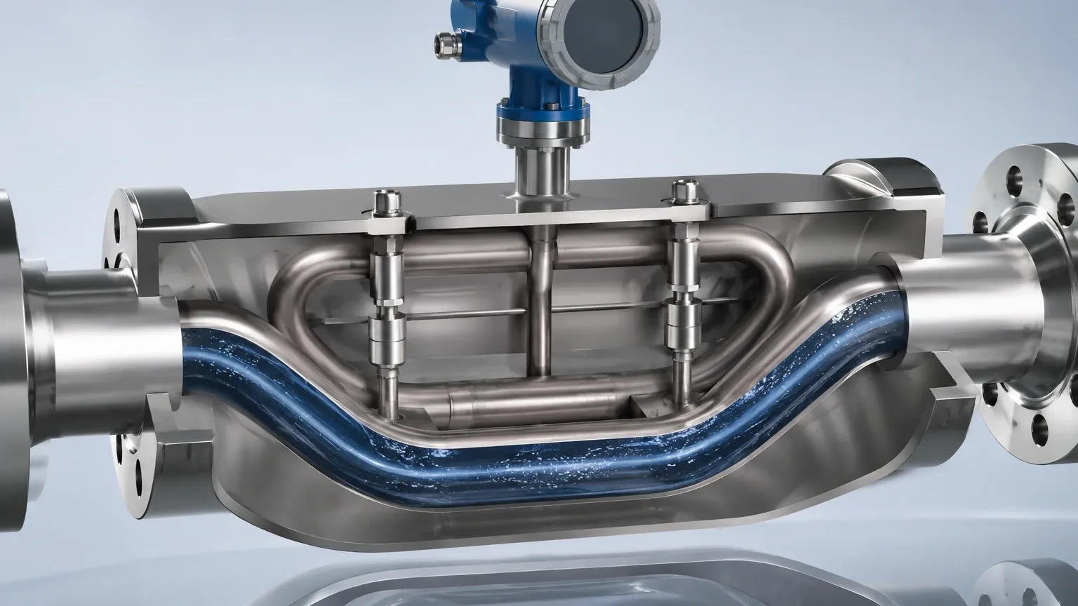
In an industrial Coriolis meter, this rotation is replaced by high-frequency vibration. The meter consists of one or more measuring tubes that are intentionally vibrated by an electromagnetic drive coil. When there is no flow, the tubes vibrate in a uniform, symmetrical manner. However, when a fluid (liquid or gas) enters the tubes, the mass of the moving fluid interacts with the vibration.
As the fluid moves toward the point of maximum vibration (the center of the tube loop), it resists being accelerated upward or downward. Conversely, as the fluid moves away from the center toward the outlet, it resists being decelerated. This creates a "twist" in the measuring tube. This mechanical distortion is known as the phase shift. The magnitude of this twist is directly proportional to the mass flow rate of the fluid passing through the device.
Mechanical Components and Signal Processing
A standard Coriolis meter comprises three primary sections: the sensor (the wetted parts), the drive system, and the transmitter (the electronics).
1. Measuring Tubes: These are typically made of stainless steel, Hastelloy, or titanium. They can be shaped like a "U," a triangle, or even a straight line. Dual-tube designs are common because they are easier to isolate from external pipeline vibrations.
2. Drive Coil: Located at the center of the tube assembly, this electromagnetic component causes the tubes to oscillate at their resonant frequency.
3. Pick-off Sensors: Usually located at the inlet and outlet sides of the tubes, these sensors (typically magnet and coil arrangements) detect the motion of the tubes. They generate a sine wave signal corresponding to the vibration.
4. The Transmitter: This is the "brain" of the unit. It compares the sine waves from the inlet and outlet pick-off sensors. When flow occurs, the inlet wave and the outlet wave become out of sync. The transmitter measures this time delay (delta-T) in microseconds.
By processing these signals, the meter calculates mass flow. For those seeking a wider range of industrial instrumentation, including level sensors that complement flow systems, visiting the Main Page of a specialized manufacturer like Welk provides access to integrated measurement solutions.
Multi-Variable Measurement Capabilities
One of the greatest advantages of Coriolis technology is its ability to measure multiple variables simultaneously. This eliminates the need for separate instruments, reducing installation costs and potential leak points.
Mass Flow Measurement
As detailed above, the phase shift between the sensors determines the mass flow. Because mass does not change with temperature or pressure, this measurement is inherently more stable than volumetric methods.
Density Measurement
The tubes are vibrated at their resonant frequency. The resonant frequency of any object depends on its mass. In a Coriolis meter, the "object" is the tube plus the fluid inside it. If the fluid density increases, the total mass of the system increases, and the vibration frequency decreases. By measuring this frequency, the meter can determine the fluid's density in real-time with high accuracy (often up to ±0.0005 g/cm³).
Temperature Measurement
Since the elasticity of the measuring tubes changes with temperature, a Coriolis meter must compensate for these changes to maintain accuracy. An integrated Resistance Temperature Detector (RTD) measures the tube temperature. This data is used for internal compensation and is also provided as an output variable for the process control system.
Practical Selection and Comparison
Selecting the right meter requires balancing accuracy requirements against the physical properties of the fluid. Below is a comparison table for common Coriolis tube configurations.
| Feature | U-Shaped Tubes | Straight-Tube Meters |
| :— | :— | :— |
| Sensitivity | Very high; larger phase shift for lower flow. | Lower; requires more sensitive electronics. |
| Pressure Drop | Higher due to the curved path. | Lower; similar to a standard pipe run. |
| Cleanability | Harder to drain; potential for sediment buildup. | Excellent; ideal for food/pharma (CIP/SIP). |
| Installation Space | Requires a larger footprint. | Compact; fits easily in tight piping. |
| Durability | Susceptible to stress at the bends. | Better resistance to mechanical stress. |
| Typical Accuracy | ±0.05% to ±0.1% | ±0.1% to ±0.2% |
Installation Considerations
To ensure the meter performs to its specified accuracy, several installation factors must be addressed:
* Orientation: For liquid applications, the tubes should ideally point downward (the "flag" or "belly down" position) to prevent gas bubbles from being trapped. For gas applications, the tubes should point upward to prevent condensate from collecting in the sensor.
* Vibration Isolation: While modern dual-tube meters are designed to cancel out internal vibrations, they can still be affected by extreme external pipeline vibrations. Using flexible connectors or robust supports on either side of the meter is recommended.
* Zero Calibration: After installation and under full-pipe, no-flow conditions, a "zero-point" calibration must be performed. This accounts for the specific mechanical stresses of the piping on the sensor.
* Straight Run Requirements: Unlike ultrasonic or turbine meters, Coriolis meters are generally not sensitive to flow profiles. This means they do not require long straight runs of pipe before or after the meter, making them ideal for compact skids.
Limitations and Challenges
Despite their versatility, Coriolis meters are not a universal solution for every application.
1. Initial Cost: The capital expenditure for a Coriolis meter is significantly higher than for an electromagnetic or vortex meter. The ROI must be justified by the need for high accuracy or multi-variable data.
2. Pressure Drop: In U-tube designs, the fluid must navigate several bends, which can result in a significant pressure drop, especially with high-viscosity liquids.
3. Gas Entrainment: While Coriolis meters can handle some gas bubbles in a liquid (and vice versa), high levels of "slug flow" or entrained air can dampen the tube vibration, causing the meter to lose its drive and stop measuring accurately.
4. Size Constraints: Coriolis meters are rarely used for pipe sizes larger than 12 inches (300 mm) due to the massive size and weight of the sensor required to maintain the necessary vibration frequency.
Frequently Asked Questions (FAQ)
Q: Can a Coriolis meter measure the flow of non-conductive liquids?
A: Yes. Unlike electromagnetic flow meters, Coriolis meters do not rely on electrical conductivity. They work on any fluid with mass, including deionized water, hydrocarbons, and liquid gases.
Q: How often does a Coriolis meter need recalibration?
A: Because there are no moving parts to wear out (like bearings in a turbine), the factory calibration is extremely stable. Most users only perform a zero-verification annually, though custody transfer applications may require more frequent validation per local regulations.
Q: Does the viscosity of the fluid affect the measurement?
A: Mass flow measurement is independent of viscosity. However, high-viscosity fluids will cause a higher pressure drop across the meter. The density measurement remains accurate regardless of viscosity.
Q: Can it measure steam?
A: While technically possible, Coriolis meters are generally not the first choice for steam due to the high temperatures and low mass of the gas, which can lead to poor signal-to-noise ratios. Vortex meters are typically more cost-effective for steam.
Conclusion
Understanding how does coriolis meter work allows process engineers to implement one of the most reliable and accurate measurement technologies available today. By providing direct mass flow, density, and temperature in a single device, Coriolis meters simplify process architecture and improve product consistency in industries ranging from chemical processing to food production.
When designing a complete fluid management system, it is essential to pair high-quality flow data with precise level measurement. For engineers looking to source industrial-grade level instruments such as radar level meters or ultrasonic sensors to work alongside their flow systems, exploring the options on the Main Page of an established manufacturer like Welk is a recommended next step. Proper selection, combined with an understanding of the Coriolis principle, ensures long-term operational efficiency and reduced maintenance costs.