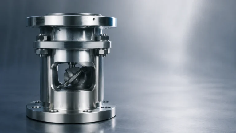
Magnetic Level Gauge with Transmitter
Magnetic Level Gauge with Transmitter
In modern industrial process control, the need for redundant, reliable, and highly visible level measurement is paramount. The magnetic level gauge with transmitter represents a hybrid solution that combines the mechanical reliability of local visual indication with the precision of electronic remote monitoring. Often referred to as a bypass level indicator, this instrument is a staple in industries ranging from oil and gas to chemical processing and water treatment. By integrating a transmitter, operators can bridge the gap between field-level manual checks and centralized control room automation.
Understanding the Measurement Principle
The operation of a magnetic level gauge with transmitter is rooted in two fundamental physical principles: buoyancy and magnetic coupling. Unlike traditional sight glasses, which rely on a transparent tube that can leak or cloud over time, the magnetic level gauge uses a completely sealed metallic or plastic chamber.
The Buoyancy Component
Inside the bypass chamber, which is connected to the process vessel via side-side, top-bottom, or other nozzle configurations, a float is designed to match the specific gravity of the process liquid. This float contains a high-intensity 360° magnetic ring. As the liquid level in the vessel rises or falls, the float moves proportionally within the chamber.
Magnetic Coupling and Visual Indication
Outside the chamber, a visual indicator—typically consisting of a series of bi-color (red/white or yellow/black) magnetic flaps or rollers—is mounted. As the float passes these flaps, the magnetic field of the float flips the flaps 180 degrees. Because the flaps are magnetically interlocked, they remain in position even if the float moves rapidly or if there is significant vibration. This provides a clear, high-contrast visual representation of the liquid level that can be read from a distance without an external power source.
The Electronic Interface (The Transmitter)
To provide a signal to a Distributed Control System (DCS) or Programmable Logic Controller (PLC), a transmitter is strapped to the outside of the chamber. This transmitter detects the position of the internal float through the chamber wall. Because the transmitter is not in contact with the process fluid, it is protected from corrosion, high pressures, and extreme temperatures, making it an exceptionally durable electronic measurement solution.
The Role of the Transmitter in Level Monitoring
When specifying a magnetic level gauge with transmitter, the choice of transmitter technology is critical for achieving the required accuracy and integration. There are two primary types of transmitters used in these assemblies:
1. Reed Chain Transmitters
Reed chain transmitters consist of a series of reed switches and resistors housed in a protective tube. As the float moves, its magnetic field closes the reed switches sequentially, changing the total resistance of the circuit. A built-in head-mounted converter then transforms this resistance into a standard 4-20mA signal.
- Resolution: Typically 5mm, 10mm, or 20mm.
- Advantages: Cost-effective, simple electronics, and highly reliable for standard monitoring tasks.
2. Magnetostrictive Transmitters
For applications requiring high precision, magnetostrictive transmitters are the preferred choice. These utilize the "time-of-flight" principle. An electronic pulse is sent down a magnetostrictive wire. When this pulse meets the magnetic field of the float, a torsional wave is generated and travels back to the sensor head. The time taken for the wave to return is used to calculate the exact position of the float.
- Resolution: Can reach ±0.5mm or better.
- Advantages: High accuracy, continuous signal, and often compatible with HART, Foundation Fieldbus, or Modbus protocols.
For engineers looking to integrate these systems into a broader automation framework, reviewing the Main Page of the manufacturer’s technical catalog is recommended to identify compatible communication protocols and housing certifications.
Selection Criteria for Industrial Applications
Selecting the correct magnetic level gauge with transmitter requires a detailed analysis of the process conditions. Because the float must be engineered to the specific gravity of the fluid, "one size fits all" does not apply.
Material Compatibility
The chamber and float must be resistant to the process media. Common materials include:
- 304/316L Stainless Steel: The standard for most industrial water and oil applications.
- Hastelloy or Titanium: Used for highly corrosive chemicals or extreme temperatures.
- Plastic (PVC, PP, PVDF): Ideal for low-pressure acid or alkali storage tanks where metallic contact must be avoided.
- PTFE/PFA Lining: Combines the structural strength of stainless steel with the chemical resistance of fluoropolymers.
Pressure and Temperature Ratings
Since the chamber is an extension of the pressure vessel, it must meet the same design codes (e.g., ASME B31.3). Standard models can often handle up to 40 bar (approx. 580 psi), but high-pressure variants can exceed 200 bar. Temperature ratings are equally critical, as extreme heat can de-magnetize the float if not properly accounted for in the material selection.
Technical Specification and Comparison Table
The following table provides a general guideline for selecting the appropriate configuration based on common industrial requirements.
| Feature | Standard Magnetic Gauge | High-Pressure/Temp Gauge | Chemical Resistant Gauge |
| :— | :— | :— | :— |
| Chamber Material | SS304 / SS316L | Heavy-wall SS316Ti / Alloy | PVC / PP / PTFE Lined |
| Max Pressure | 40 bar | Up to 250 bar | 6 – 10 bar |
| Max Temperature | 150°C | Up to 450°C | 60°C – 100°C |
| Transmitter Type | Reed Chain (4-20mA) | Magnetostrictive (HART) | Reed Chain (Plastic Housing) |
| Accuracy | ±10mm (Visual) | ±1mm (Transmitter) | ±5mm (Transmitter) |
| Typical Fluid | Water, Diesel, Oil | Steam, Hydrocarbons | Acids, Bleach, Caustics |
Installation Guidelines and Best Practices
Proper installation is essential to ensure the float moves freely and the transmitter provides accurate data. Failure to follow these guidelines often results in "stuck" floats or signal interference.
1. Vertical Alignment: The bypass chamber must be installed perfectly vertical. Even a slight tilt can cause the float to rub against the chamber wall, leading to friction and eventual sticking. Use a spirit level during the mounting process.
2. Magnetic Interference: Keep the gauge away from large ferrous structures or high-voltage cables. External magnetic fields can interfere with the coupling between the float and the visual flags or the transmitter.
3. Isolation Valves: It is highly recommended to install isolation valves (ball or gate valves) between the vessel and the gauge. This allows for maintenance or cleaning without draining the main tank.
4. Venting and Draining: Ensure the gauge has a vent plug at the top and a drain valve at the bottom. This is necessary for commissioning (removing air pockets) and for periodic flushing of sediment.
5. Transmitter Positioning: The transmitter should be mounted on the side of the chamber, typically 90 degrees away from the visual indicator, to ensure it captures the magnetic field effectively without obstructing the view.
Limitations and Common Risks
While the magnetic level gauge with transmitter is a robust tool, it is not suitable for every application. Engineers should be aware of the following limitations:
* Magnetic Particles: If the process fluid contains iron filings or magnetic scales, these particles will adhere to the float's magnetic ring. Over time, this buildup will increase the float's weight (changing its buoyancy) and may eventually jam it against the chamber wall. Magnetic filters/traps should be used in these cases.
* High Viscosity: Extremely viscous liquids can impede the movement of the float. If the fluid "sticks" to the float and the chamber wall, the response time will lag significantly.
* Coating and Scaling: In applications like wastewater or lime slurry, the internal walls of the chamber can become coated. While the magnetic field can pass through the coating, a thick layer can physically restrict the float.
* Specific Gravity Changes: Since the float is weighted for a specific density, significant changes in the fluid's composition (e.g., switching from oil to water in the same tank) will result in measurement errors.
Frequently Asked Questions (FAQ)
Q: Can a transmitter be added to an existing magnetic level gauge?
A: Yes, in most cases, a transmitter can be retrofitted to an existing gauge. Since it is externally mounted, there is no need to break the pressure boundary or stop the process. However, you must ensure the transmitter is compatible with the magnetic field strength of the existing float.
Q: What is the difference between a reed chain and a magnetostrictive transmitter in terms of maintenance?
A: Reed chains are generally maintenance-free but have a finite mechanical life for the reed switches. Magnetostrictive transmitters are solid-state and typically offer longer service lives and better diagnostic capabilities (such as signal strength monitoring).
Q: How do I calibrate the transmitter?
A: Most modern transmitters are calibrated at the factory based on the center-to-center distance of the gauge's nozzles. Field calibration usually involves setting the 4mA point (Zero) at the bottom process connection and the 20mA point (Span) at the top connection using a handheld communicator or local push-buttons.
Q: Are these units suitable for hazardous areas?
A: Yes, magnetic level gauges with transmitters are frequently used in explosive atmospheres. Transmitters are available with ATEX, IECEx, or UL certifications, featuring either Intrinsically Safe (Ex i) or Explosion-Proof (Ex d) protection methods.
Conclusion
The magnetic level gauge with transmitter offers a unique combination of safety, visibility, and automation. By eliminating the risks associated with fragile glass indicators and providing a non-contact electronic interface, it remains one of the most reliable methods for liquid level management in demanding environments. When selecting a system, prioritize material compatibility and the required precision of the transmitter to ensure long-term operational success. For further technical specifications and to review product options and application support, please refer to the Main Page for detailed engineering data.