Magnetic Level Sensor
Magnetic Level Sensor
In the landscape of industrial process control, the magnetic level sensor represents a critical intersection of mechanical simplicity and magnetic physics. These instruments provide reliable, real-time monitoring of liquid levels in tanks and vessels, often serving as the primary safety or operational interface in high-pressure or corrosive environments. Unlike traditional sight glasses, which are prone to breakage and leakage, magnetic level measurement systems offer a sealed solution that prevents process fluid from contacting the external environment or the viewing apparatus.
For engineers and plant managers, selecting a magnetic level sensor requires a deep understanding of fluid dynamics, material science, and magnetic coupling. This guide provides a technical overview of how these systems operate, how to specify them for diverse industrial applications, and the best practices for ensuring long-term accuracy.
Understanding the Magnetic Level Sensor Principle
The operation of a magnetic level sensor is based on two fundamental physical concepts: Archimedes’ Principle of Buoyancy and the interaction of magnetic fields.
The Buoyancy Component
At the core of the system is a float, which is engineered to have a lower density than the process liquid. This float resides within a non-magnetic chamber (usually a bypass pipe or a stilling well) that is connected to the process vessel. As the liquid level in the vessel rises or falls, the liquid level in the chamber moves accordingly, causing the float to move in tandem.
The Magnetic Coupling
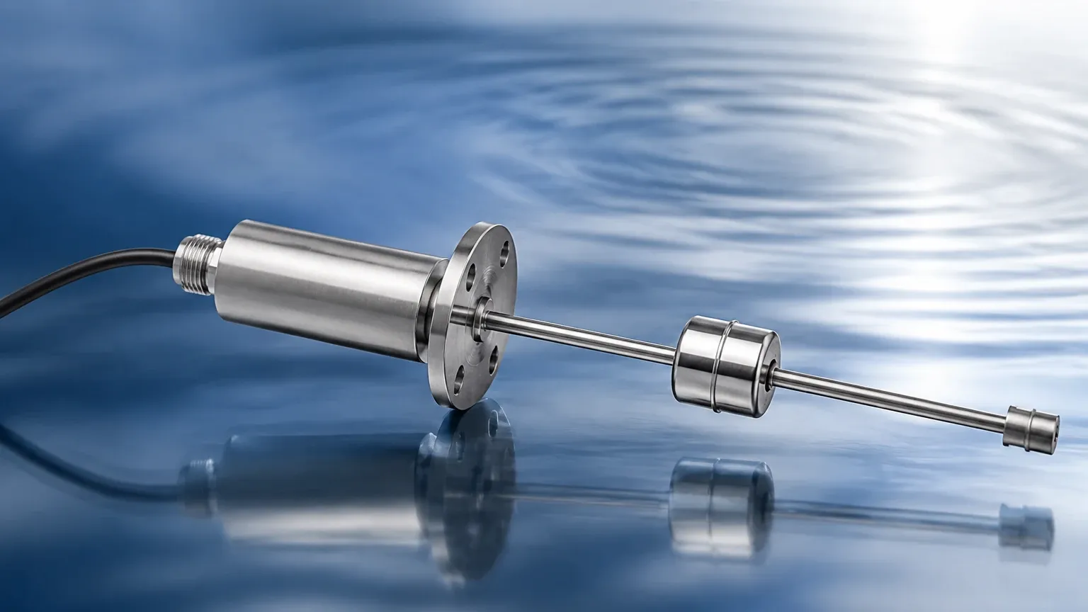
Inside the float is a permanent magnet assembly. Outside the chamber, a secondary device—either a visual indicator, a series of reed switches, or a continuous transmitter—is mounted. Because the chamber wall is made of non-magnetic material (such as 304 or 316L stainless steel, or specialized plastics), the magnetic field from the float passes through the wall without interference. This "magnetic coupling" allows the internal float position to be translated into an external reading or electrical signal without any physical penetration of the chamber wall, maintaining a hermetic seal.
Key Components and Design Variations
A complete magnetic level sensor system typically consists of several integrated components, each of which must be specified based on the application requirements.
1. The Measurement Chamber
The chamber is the pressure-retaining vessel that houses the float. In a bypass configuration, the chamber is mounted to the side of the tank via process flanges. In top-mount configurations, the chamber extends into the tank. Standard chambers are constructed from stainless steel, but for highly corrosive media, materials like Hastelloy, Titanium, or PVC/PVDF are used.
2. The Internal Float
The float is the most sensitive part of the sensor. It must be designed to withstand the process pressure while remaining buoyant. For high-pressure applications (up to 200 bar or 2900 psi), floats are often constructed as reinforced spheres or cylinders. The magnetic assembly inside the float is positioned precisely at the liquid's surface level (the immersion point) to ensure accuracy.
3. Visual Indicators (Magnetic Level Gauges)
For local monitoring, a visual indicator is attached to the outside of the chamber. This often consists of a series of bi-color (usually red and white) magnetic flaps or rollers. As the float passes, the magnetic field flips the flaps 180 degrees, changing the color and providing a clear, high-visibility representation of the liquid level. These require no power to operate, making them ideal for emergency monitoring.
4. Electrical Transmitters and Switches
To integrate the sensor into a control system (PLC/DCS), external transmitters are added.
* Reed Switch Chains: A series of switches that provide a stepped resistance output (e.g., 4-20mA).
* Magnetostrictive Transmitters: These offer high-precision, continuous level measurement by measuring the time-of-flight of a sonic pulse triggered by the float's magnetic field.
* Point Level Switches: Individual magnetic switches can be clamped to the chamber at specific heights to trigger high or low-level alarms.
Selection Criteria for Industrial Applications
Choosing the correct magnetic level sensor involves more than just matching pipe sizes. Engineers must evaluate several environmental and fluid-specific factors to avoid premature failure.
Fluid Density (Specific Gravity)
The float must be lighter than the liquid it measures. If the liquid density is too low (e.g., liquefied gases or light hydrocarbons), a standard float may sink. Custom-weighted floats are often required for fluids with a specific gravity below 0.5.
Operating Temperature and Pressure
High temperatures can affect the strength of the magnets (approaching the Curie point) and the structural integrity of the float. Conversely, high pressure can crush a float that is not properly rated. Standard industrial units typically handle temperatures from -196°C to +450°C.
Material Compatibility
The chamber and float materials must be chemically compatible with the process fluid. For example, 316L stainless steel is standard for water and many oils, but sulfuric acid applications may require PVDF or PTFE-lined chambers.
Practical Selection Table
| Application Type | Recommended Material | Pressure Range | Temperature Range | Typical Industry |
| :— | :— | :— | :— | :— |
| Water Treatment | 304/316 Stainless Steel | Up to 40 bar | -20°C to 150°C | Municipal / Power |
| Corrosive Chemicals | PVC / PVDF / PP | Up to 6 bar | -10°C to 80°C | Chemical Processing |
| High-Pressure Steam | Reinforced 316L / Alloy | Up to 160 bar | Up to 400°C | Oil & Gas / Boilers |
| Cryogenic Liquids | Stainless Steel (Insulated) | Up to 25 bar | Down to -196°C | Industrial Gas |
Installation Best Practices and Maintenance
Proper installation is paramount to the accuracy of a magnetic level sensor. Because the system relies on a free-moving float, mechanical alignment is the most common point of failure.
Orientation and Verticality
The measurement chamber must be installed perfectly vertical. Even a slight tilt can cause the float to rub against the chamber walls, leading to friction, wear, and eventually a "stuck" float. Use a precision level during installation to ensure verticality within ±0.5 degrees.
Magnetic Interference
Since the sensor operates on magnetic coupling, it must be kept away from large ferrous structures or high-voltage electrical equipment that could generate stray magnetic fields. A minimum clearance of 100mm (4 inches) from steel supports or other magnetic gauges is generally recommended.
Bypass Piping Considerations
When using a bypass configuration, ensure that the isolation valves are full-port types to prevent flow restrictions. Vent and drain valves should be installed at the top and bottom of the chamber to allow for safe maintenance and calibration without shutting down the main process vessel.
Maintenance Checklist
1. Chamber Flushing: Periodically drain the chamber to remove sediment or scale that could impede float movement.
2. Float Inspection: In applications with vibrating equipment, inspect the float for signs of mechanical fatigue or magnetic degradation.
3. Indicator Alignment: Ensure the visual indicator scale has not shifted and that the flaps move freely.
Limitations and Operational Risks
While highly versatile, the magnetic level sensor is not suitable for every application. Understanding these limitations prevents costly engineering errors.
* Viscosity and Coating: Highly viscous liquids (above 500 cP) can slow the float's response or cause it to stick. Similarly, fluids that leave a heavy coating or crystalline deposit on the chamber walls can jam the float.
* Magnetic Particles: If the process fluid contains ferrous particles (e.g., iron filings or magnetite), these particles will be attracted to the float's magnet. This buildup can increase the float's weight or cause it to wedge against the chamber wall. Magnetic traps or filters should be installed upstream in these cases.
* Turbulence: In tanks with heavy agitation, a bypass chamber or a stilling well is mandatory to protect the float from mechanical damage and to ensure a stable reading.
Frequently Asked Questions
Q: Can a magnetic level sensor be used for interface measurement (e.g., oil and water)?
A: Yes. By precisely weighting the float to a density that is between the densities of the two liquids (e.g., 0.85 SG for an oil/water interface), the float will sink through the upper layer and float on the lower layer.
Q: What happens if the float is installed upside down?
A: Most floats are directional because the magnet assembly is positioned relative to the immersion point. Installing a float upside down will result in significant measurement errors or a failure of the magnetic coupling with the indicator.
Q: How do I choose between a reed switch transmitter and a magnetostrictive transmitter?
A: Reed switch transmitters are cost-effective and sufficient for general level monitoring with 5mm to 10mm resolution. Magnetostrictive transmitters are preferred for high-precision applications requiring sub-millimeter accuracy and faster response times.
Q: Do magnetic level gauges require calibration?
A: The visual indicator is purely mechanical and does not require calibration. However, the external electrical transmitters (4-20mA) should be calibrated periodically to ensure the signal matches the physical level shown on the gauge.
Conclusion
The magnetic level sensor remains a cornerstone of industrial level measurement due to its robust design and the safety provided by its pressure-tight construction. By eliminating the risks associated with direct-contact glass gauges, it provides a reliable solution for even the most hazardous fluids. When specifying these instruments, careful attention to fluid density, pressure ratings, and material compatibility is essential for operational success. For more detailed technical specifications and to Review product options and application support, consulting with a specialized manufacturer like Welk can help ensure the selected instrument meets the specific demands of your facility's infrastructure.