Non Invasive Water Flow Meter
Non Invasive Water Flow Meter
In modern industrial process control, the ability to measure fluid velocity without interrupting operations or compromising the integrity of piping systems is a significant advantage. A non invasive water flow meter, typically utilizing ultrasonic technology, allows for precise measurement from the outside of a pipe. This technology eliminates the need for pipe cutting, welding, or process downtime, making it a preferred choice for retrofitting existing systems and for applications where hygiene or chemical compatibility is paramount.
For engineers and facility managers, understanding the underlying principles, selection criteria, and installation nuances of these devices is essential for ensuring long-term measurement accuracy. This guide explores the technical framework of non-invasive flow measurement and provides practical insights for industrial implementation.
Understanding Measurement Principles
Non-invasive flow measurement primarily relies on ultrasonic waves to determine the velocity of water within a closed conduit. There are two dominant technologies used in this field: Transit-Time and Doppler Effect.
Transit-Time Ultrasonic Principle
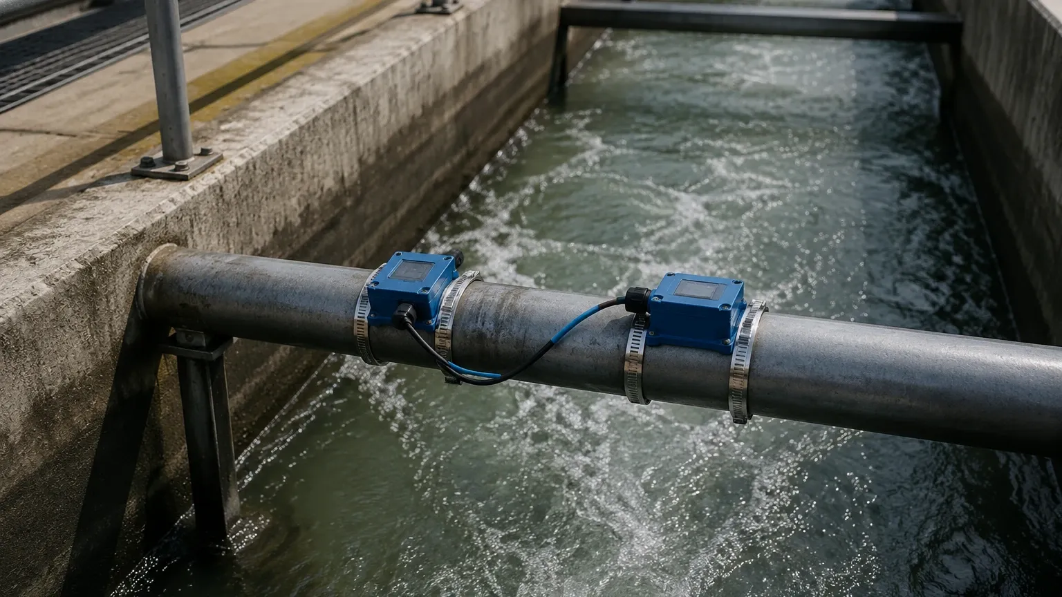
Most clean water applications utilize the transit-time (or time-of-flight) principle. This method employs a pair of ultrasonic transducers clamped to the outside of the pipe. Each transducer functions as both a transmitter and a receiver.
When the water is stationary, the time it takes for an ultrasonic pulse to travel from Transducer A to Transducer B is identical to the time from B to A. However, when water is flowing, the pulse traveling with the flow (downstream) moves faster than the pulse traveling against the flow (upstream). The flow meter measures this extremely small time difference—often in nanoseconds—which is directly proportional to the flow velocity. By integrating the pipe’s cross-sectional area, the device calculates the volumetric flow rate (e.g., m³/h or GPM).
Doppler Effect Principle
While transit-time meters require relatively clean water to allow the ultrasonic signal to pass through, Doppler flow meters rely on reflections. They emit sound waves that bounce off suspended solids or entrained air bubbles (aeration) in the water. The frequency shift of the reflected signal is used to calculate velocity. While less common for treated water, Doppler technology is essential for wastewater or slurries where transit-time signals would be attenuated.
Key Selection Criteria for Industrial Applications
Selecting the correct non invasive water flow meter requires a detailed assessment of the physical environment and the fluid properties. Unlike inline meters, the pipe itself acts as part of the measurement system.
1. Pipe Material and Condition
Ultrasonic signals must pass through the pipe wall and any internal lining. Standard materials like carbon steel, stainless steel, ductile iron, and most plastics (PVC, PE, PVDF) are excellent conductors of ultrasonic waves. However, pipes with thick internal liners—such as cement or bitumen—can pose challenges if the liner is not well-bonded to the pipe wall. Air gaps between the liner and the pipe will reflect the signal, preventing measurement.
2. Pipe Size and Wall Thickness
Transducers are typically categorized by the pipe diameters they support. Small-bore transducers may cover 15 mm to 100 mm (0.5" to 4"), while large-scale transducers can handle pipes up to 6,000 mm (236"). Accurate wall thickness measurement is critical; even a 1 mm error in thickness input can lead to significant flow calculation errors.
3. Fluid Characteristics
For a transit-time non invasive water flow meter to function, the fluid must be sonically conductive. It should ideally contain less than 2% total suspended solids (TSS) or aeration. If the water contains high concentrations of bubbles or debris, a Doppler-based system or a high-performance transit-time meter with advanced digital signal processing (DSP) is required.
Installation Best Practices and Configurations
The performance of a non-invasive meter is heavily dependent on the quality of the installation. Because the sensors are not in contact with the fluid, the interface between the transducer and the pipe is the most critical link.
Transducer Mounting Methods
There are three primary mounting configurations used depending on the pipe size and signal strength:
* V-Method: The most common setup for pipes between 25 mm and 400 mm. The signal crosses the pipe twice, reflecting off the opposite wall. It provides a good balance between signal strength and accuracy.
* Z-Method: Used for large pipes (typically >400 mm) or where the fluid is slightly attenuating. Transducers are placed on opposite sides of the pipe, and the signal crosses only once.
* W-Method: Reserved for very small pipes (under 50 mm). The signal bounces four times, increasing the path length to improve resolution in low-flow conditions.
Straight Pipe Run Requirements
To ensure a stable and repeatable flow profile, the meter must be installed away from turbulence-inducing components. The standard engineering guideline is the "10D Upstream / 5D Downstream" rule. This means the meter should be placed at a distance of at least 10 times the pipe diameter after a bend or valve, and 5 times the diameter before the next fitting. If the flow is heavily disturbed (e.g., after a partially open valve or a pump), upstream requirements may increase to 20D or 30D.
Coupling Compounds
Since air is a poor conductor of high-frequency sound, a coupling compound (ultrasonic grease or gel) must be applied between the transducer face and the pipe surface. For permanent installations, high-temperature silicone or solid foil pads are often used to prevent the couplant from drying out over time.
Comparison: Non-Invasive vs. Inline Flow Meters
| Feature | Non-Invasive (Clamp-on) | Inline (Electromagnetic/Turbine) |
| :— | :— | :— |
| Installation Cost | Low (No pipe cutting) | High (Requires plumbing/downtime) |
| Pressure Drop | Zero | Variable (Depends on meter type) |
| Maintenance | Low (No moving parts) | Moderate (Wear and tear/clogging) |
| Accuracy | 0.5% to 2.0% of rate | 0.2% to 1.0% of rate |
| Fluid Compatibility | Limited by sonic conductivity | Limited by electrical conductivity/corrosion |
| Pipe Pressure | No limit (External) | Limited by flange/body rating |
Limitations and Common Challenges
While highly versatile, the non invasive water flow meter is not a universal solution. Engineers must be aware of the following limitations:
1. Signal Attenuation: Highly viscous liquids or those with high concentrations of entrained air can absorb the ultrasonic signal.
2. Pipe Scaling: Internal scaling or heavy rust can scatter the ultrasonic beam. In older municipal water lines, it may be necessary to grind the pipe surface to bright metal before mounting transducers.
3. Temperature Extremes: Standard transducers are rated for -30°C to +90°C. High-temperature applications (e.g., boiler feed water at 200°C) require specialized transducers and mounting hardware.
4. Ambient Noise: In some heavy industrial environments, high-frequency mechanical vibration can interfere with the ultrasonic signal, though modern DSP filters mitigate much of this.
Integration with Level Measurement Systems
In many water treatment and chemical processing plants, flow measurement is used in conjunction with level measurement to provide a complete picture of mass balance. For instance, monitoring the inflow to a tank via a non-invasive meter while tracking the tank's volume with a radar or ultrasonic level sensor allows for leak detection and inventory management.
As a professional manufacturer of industrial instrumentation, Welk provides a range of solutions including radar level meters and ultrasonic level sensors that complement flow monitoring systems. For detailed technical specifications on level measurement integration, you can Review product options and application support at our Main Page.
Frequently Asked Questions (FAQs)
Q: Can a non invasive water flow meter work on plastic pipes?
A: Yes, ultrasonic waves travel well through most plastics including PVC, HDPE, and PP. It is important to ensure the pipe is full of liquid and the wall thickness is accurately measured.
Q: Does the meter require periodic recalibration?
A: Because there are no moving parts to wear out and no contact with the fluid, the electronic calibration remains stable. However, it is recommended to check the coupling gel every 12-24 months in permanent installations to ensure signal strength remains optimal.
Q: What is the minimum flow velocity required?
A: Most modern industrial clamp-on meters can detect velocities as low as 0.01 m/s (0.03 ft/s), though accuracy typically improves as the velocity exceeds 0.3 m/s (1 ft/s).
Q: Can it measure flow in partially filled pipes?
A: Standard transit-time and Doppler clamp-on meters require the pipe to be 100% full to provide an accurate volumetric reading. If the pipe is partially full, the meter will either report an error or provide an incorrect reading based on a full cross-section.
Q: How do I handle pipes with thick paint or coatings?
A: Thick or loose paint should be removed from the area where the transducers will be mounted. A thin, well-bonded layer of paint usually does not interfere with the signal, but any flaking or air pockets will block the ultrasound.
By adhering to these technical guidelines and carefully evaluating the installation site, a non invasive water flow meter provides a reliable, cost-effective, and highly flexible solution for industrial water management.