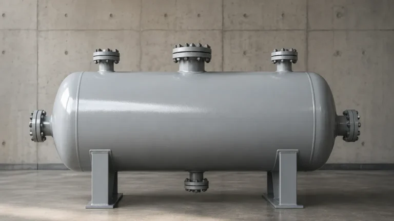
Magnetic Liquid Level Gauge
Magnetic Liquid Level Gauge
In the landscape of industrial process control, the ability to monitor fluid levels accurately and safely is paramount. Among the various technologies available, the magnetic liquid level gauge (MLG) stands out as a robust, low-maintenance, and highly visible solution for both local indication and remote monitoring. Unlike traditional sight glasses, which are prone to leaks and breakage, the magnetic liquid level gauge utilizes a sealed chamber and magnetic coupling to provide a clear visual representation of the liquid level, even in high-pressure or hazardous environments.
This guide provides a comprehensive technical overview of the magnetic liquid level gauge, covering its operating principles, component selection, installation best practices, and limitations to assist engineers and plant operators in making informed procurement decisions. For a broader overview of industrial instrumentation, you may visit our Main Page to explore our full range of measurement solutions.
Measurement Principles and Operation
The operation of a magnetic liquid level gauge is based on two fundamental physical principles: buoyancy and magnetism.
The Buoyancy Principle
The device consists of a bypass chamber (the standpipe) connected to the side of a vessel. According to the law of communicating vessels, the liquid level inside the chamber matches the liquid level in the main tank. Inside this chamber is a cylindrical float. The float is engineered with a specific buoyancy to ensure it floats on the surface of the process liquid. Its weight and volume are calculated based on the density (specific gravity) of the medium it will measure.
Magnetic Coupling
Inside the float is a high-strength permanent magnet, typically arranged in a 360-degree ring configuration. Mounted to the outside of the chamber is an indicator rail. This rail contains a series of small, bi-color (usually red and white) magnetic flaps or rollers. As the liquid level rises or falls, the float moves accordingly. The magnetic field from the float passes through the non-magnetic chamber wall (usually stainless steel or plastic) and acts upon the flaps.
When the float passes a flap, the magnetic attraction causes the flap to rotate 180 degrees. This change in orientation switches the visible color of the flap—typically from white (representing air/gas) to red (representing liquid). Because the coupling is magnetic, there is no direct contact between the process fluid and the indicator, eliminating the risk of leaks associated with glass tube gauges.
Key Components of a Magnetic Liquid Level Gauge
Understanding the construction of these instruments is essential for selecting the right model for a specific application. A standard assembly includes the following:
1. The Chamber: A vertical pipe connected to the vessel via process connections (flanges or NPT threads). It must be made of a non-magnetic material to allow the magnetic field to pass through to the indicator.
2. The Float: The most critical component. It must be resistant to the process temperature, pressure, and chemical corrosiveness. Floats are often pressurized or reinforced for high-pressure applications.
3. The Indicator Rail: A sealed housing containing the magnetic flaps. These are often made of aluminum or stainless steel for durability, with the flaps themselves made of plastic or ceramic depending on the ambient temperature.
4. Transmitters and Switches (Optional): To integrate the gauge into a control system (PLC/DCS), a reed-chain transmitter or magnetostrictive transmitter can be strapped to the chamber. These provide a 4-20mA or digital signal (HART, Modbus) corresponding to the level. Magnetic switches can also be added for high/low-level alarms.
Practical Selection Table
When specifying a magnetic liquid level gauge, several variables must be balanced. The following table outlines typical configurations based on application requirements:
| Application Type | Chamber Material | Float Material | Max Pressure (Typical) | Max Temperature | Notes |
| :— | :— | :— | :— | :— | :— |
| Standard Water/Oil | 304/316 Stainless Steel | 316L Stainless Steel | 40 bar (4 MPa) | 150°C | Most common industrial configuration. |
| Corrosive Chemicals | PVC / PP / PVDF | PTFE or PVDF | 6 bar (0.6 MPa) | 60°C – 100°C | Used for acids and bases where metals fail. |
| High Pressure | Heavy-wall 316SS / Titanium | Titanium (Reinforced) | 200+ bar (20 MPa) | 400°C | Requires specialized float design to prevent crushing. |
| Cryogenic | 316 Stainless Steel | Stainless Steel | 25 bar (2.5 MPa) | -196°C | Requires vacuum-jacketed insulation to prevent icing. |
| Interface Level | 316 Stainless Steel | Weighted 316L | 40 bar (4 MPa) | 200°C | Float is weighted to sink in the top liquid and float on the bottom liquid. |
Installation Considerations
Proper installation is vital for the longevity and accuracy of a magnetic liquid level gauge. Engineers should adhere to the following guidelines:
* Verticality: The chamber must be installed perfectly vertical. Even a slight tilt can cause the float to rub against the chamber walls, leading to friction and potential sticking.
* Isolation Valves: It is highly recommended to install isolation valves (ball or gate valves) between the vessel and the gauge. This allows for maintenance or float replacement without draining the entire tank.
* Venting and Draining: The chamber should be equipped with a vent plug at the top and a drain valve at the bottom. This facilitates the removal of air pockets during startup and the flushing of sediment during maintenance.
* Magnetic Interference: Keep the gauge away from large motors, high-voltage cables, or other sources of strong electromagnetic fields, as these can interfere with the magnetic coupling between the float and the indicator.
* Clearance: Ensure there is enough overhead or bottom clearance to remove the float from the chamber for inspection.

Limitations and Operational Risks
While the magnetic liquid level gauge is highly versatile, it is not suitable for every application. Awareness of its limitations prevents operational failures:
1. Magnetic Particles: If the process fluid contains ferromagnetic particles (e.g., iron filings or magnetite), these particles will adhere to the float's magnet. Over time, this buildup will increase the float's weight and eventually cause it to jam inside the chamber.
2. High Viscosity: Extremely viscous liquids can impede the movement of the float. In such cases, the gauge may require a larger chamber diameter or internal heating (steam jackets) to reduce viscosity.
3. Coating and Scaling: If the liquid tends to crystallize or leave heavy deposits, the float may become stuck. Regular flushing via the drain valve is necessary in these environments.
4. Specific Gravity Changes: Since the float is designed for a specific liquid density, any significant change in the fluid composition (and thus its density) will result in measurement errors. If the density drops below the float's design limit, the float will sink.
Frequently Asked Questions (FAQs)
1. How do I calibrate a magnetic liquid level gauge?
One of the primary advantages of a magnetic liquid level gauge is that the visual indicator itself does not require calibration; it is a purely mechanical/magnetic reaction. However, if a 4-20mA transmitter is attached, it must be calibrated by aligning the 4mA point with the zero mark on the scale and the 20mA point with the maximum level mark.
2. Can I use a magnetic level gauge for interface measurement?
Yes. By specifically weighting the float so that its density is between the densities of the two immiscible liquids (e.g., oil and water), the float will sit at the interface layer. This provides a clear visual of where the two liquids meet.
3. What maintenance is required?
Under normal conditions, maintenance is minimal. Periodic flushing of the chamber to remove sediment is recommended. If the indicator flaps become dirty or faded due to UV exposure, the indicator rail can usually be replaced or cleaned without opening the process chamber.
4. What happens if the float is installed upside down?
If the float is inverted, the internal magnet will likely be at the wrong height relative to the liquid surface, leading to a constant offset in the reading. Most floats are clearly marked with "TOP" or an arrow to prevent this error.
5. Can these gauges handle extreme temperatures?
Yes, but material selection is key. For high temperatures, ceramic flaps are used instead of plastic ones. For cryogenic applications, a specialized insulation jacket is used to prevent frost from forming over the indicator, which would otherwise obscure the reading.
Conclusion
The magnetic liquid level gauge remains a cornerstone of industrial level measurement due to its simplicity, safety, and reliability. By eliminating the risks of glass breakage and providing both local and remote data, it serves as an ideal solution for challenging process conditions. When selecting a gauge, it is critical to provide accurate data regarding liquid density, operating pressure, and temperature to ensure the float and chamber are engineered for the task.
For technical support, custom OEM services, or to view our full catalog of radar, ultrasonic, and magnetic measurement instruments, please refer to our Main Page. Welk provides high-quality, cost-effective solutions tailored to the needs of water treatment, chemical processing, and industrial automation worldwide.