Mccrometer Insertion Mag
Mccrometer Insertion Mag
In the landscape of industrial fluid management, the ability to measure flow accurately in large-diameter piping systems presents a significant engineering challenge. Traditional full-bore magnetic flowmeters, while highly accurate, become prohibitively expensive and difficult to install as pipe sizes increase. The mccrometer insertion mag technology addresses these challenges by providing a versatile, cost-effective, and high-performance alternative for municipal water, irrigation, and industrial process applications. This guide explores the technical principles, selection criteria, and installation requirements for insertion electromagnetic flowmeters.
Understanding the Electromagnetic Measurement Principle
Before evaluating specific hardware, it is essential to understand the underlying physics that govern the mccrometer insertion mag. Like all electromagnetic flowmeters (mag meters), these devices operate based on Faraday’s Law of Electromagnetic Induction. This principle states that a conductor moving through a magnetic field produces an electrical voltage proportional to the velocity of the conductor.
In the context of a flowmeter, the "conductor" is the flowing liquid itself. For the measurement to be successful, the liquid must have a minimum level of electrical conductivity, typically at least 5 to 20 microsiemens per centimeter (µS/cm).
The Mathematical Foundation
The relationship is defined by the equation:
E = k × B × D × v
Where:
* E is the induced voltage.
* k is a constant specific to the meter design.
* B is the strength of the magnetic field.
* D is the distance between the electrodes (or the pipe diameter in full-bore versions).
* v is the average velocity of the liquid.
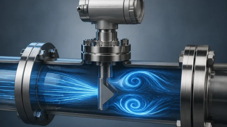
In an insertion mag meter, the sensor probe is inserted into the pipe through a mounting nipple. The probe contains coils that generate a magnetic field and electrodes that detect the voltage induced by the passing fluid. Unlike full-bore meters that measure the entire flow stream, insertion meters measure the velocity at a specific point or along a specific profile, which is then used to calculate the total volumetric flow rate based on the pipe's cross-sectional area.
Key Advantages of Insertion Technology
The mccrometer insertion mag is often selected over other flow technologies due to several distinct advantages in B2B and industrial environments:
1. Cost-Efficiency in Large Pipes: For pipes exceeding 200 mm (8 inches), the cost of a full-bore mag meter rises exponentially. Insertion meters maintain a relatively flat cost curve regardless of pipe size, as the sensor probe remains the same size while only the mounting hardware changes.
2. Ease of Installation (Hot-Tapping): One of the most significant benefits is the ability to install the meter without shutting down the process. Through a process known as "hot-tapping," a hole is drilled into the pressurized pipe through a valve, and the probe is inserted. This eliminates downtime and the need for heavy machinery required to cut and flange large pipe sections.
3. Low Pressure Drop: Because the probe occupies only a tiny fraction of the pipe's cross-sectional area, the permanent pressure loss is negligible compared to orifice plates or Venturi meters.
4. Versatility: These meters can be used in a wide range of pipe materials, including steel, ductile iron, PVC, and concrete (with appropriate grounding).
Selection Criteria and Technical Specifications
Choosing the right mccrometer insertion mag requires a detailed analysis of the application's hydraulic profile and fluid characteristics. Engineers should use the following table as a baseline for evaluating whether an insertion mag meter is suitable for their specific project.
Practical Selection Table
| Feature | Specification / Requirement |
| :— | :— |
| Pipe Size Range | 75 mm to 3,000 mm (3" to 120") |
| Fluid Conductivity | Minimum 5 µS/cm (Typical) |
| Accuracy | ±0.5% to ±2% of reading (depending on model and profile) |
| Flow Velocity Range | 0.1 m/s to 10 m/s (0.3 ft/s to 32 ft/s) |
| Maximum Pressure | Up to 17 bar (250 psi) standard; higher options available |
| Wetted Materials | Stainless Steel, Hastelloy, NSF-certified coatings |
| Output Signals | 4-20mA, Pulse, Modbus, HART, Sensus/Itron protocols |
When planning a comprehensive fluid management system, it is often necessary to pair flow data with level data. For those managing bulk storage or open-channel transitions, reviewing specialized instrumentation via the Main Page of a dedicated manufacturer can provide the necessary context for integrating these two critical data points.
Installation Considerations and Best Practices
The accuracy of an insertion mag meter is highly dependent on its placement and the stability of the flow profile. Because the meter samples velocity at a specific point, any turbulence or swirl in the pipe will lead to measurement errors.
Straight Run Requirements
To ensure a fully developed flow profile, the meter must be installed with sufficient straight pipe runs upstream and downstream of the sensor. Standard guidelines recommend:
* Upstream: 10 diameters (10D) of straight pipe after common obstructions like elbows or valves.
* Downstream: 5 diameters (5D) of straight pipe before any subsequent fittings.
If the installation site cannot meet these requirements, flow conditioners or specific multi-electrode insertion meters (which measure the velocity profile across the entire diameter) may be necessary to maintain accuracy.
Orientation and Depth
* Horizontal Pipes: The probe should ideally be installed at the 2 o'clock or 10 o'clock position. Avoid the very top (where air bubbles may collect) and the very bottom (where sediment may accumulate and coat the electrodes).
* Vertical Pipes: Flow should always move upward to ensure the pipe remains completely full. Measuring downward flow is generally discouraged as the pipe may not be full, leading to significant over-reading.
* Insertion Depth: Precise depth is critical. Most manufacturers provide a calculation based on the pipe's internal diameter (ID) to locate the sensor at the point of average velocity, typically around 1/8th or 1/12th of the diameter depending on the flow profile.
Grounding
Since the meter measures micro-voltages, electrical noise can interfere with the signal. Proper grounding is mandatory. If the pipe is conductive (e.g., unlined steel), the meter can be grounded directly to the pipe. If the pipe is non-conductive (e.g., PVC or lined pipe), grounding rings or electrodes must be used to ensure the fluid is at the same electrical potential as the meter electronics.
Limitations and Common Risks
While the mccrometer insertion mag is a robust tool, it is not a "one-size-fits-all" solution. Engineers must be aware of the following limitations:
* Non-Conductive Fluids: These meters will not work with oils, deionized water, or most hydrocarbons. In these cases, ultrasonic or turbine meters are preferred.
* Particulate Build-up: While mag meters have no moving parts, the electrodes can become coated with grease, scale, or bio-films in wastewater applications. This coating insulates the electrodes and causes the signal to drift or fail.
* Profile Sensitivity: Unlike full-bore meters, insertion meters are sensitive to changes in the Reynolds number and the velocity profile. If the flow transitions from laminar to turbulent or if there is significant swirl, the accuracy will degrade.
* Air Pockets: The presence of air in the line is the primary enemy of electromagnetic measurement. Air is non-conductive; if an air bubble passes over an electrode, the circuit is broken, leading to erratic readings.
Maintenance and Troubleshooting
One of the primary reasons for selecting a mag meter is the lack of moving parts, which significantly reduces maintenance requirements. However, a periodic check-up is recommended to ensure long-term reliability.
1. Electrode Cleaning: If the fluid is known to cause scaling, the probe should be retracted (using the hot-tap valve) and cleaned with a soft cloth or appropriate solvent annually.
2. Transmitter Calibration: While the sensor's "K-factor" is stable, the electronic transmitter should be verified using a signal simulator to ensure the 4-20mA output correctly corresponds to the flow rate.
3. Insulation Resistance Test: If readings become erratic, a technician should check the insulation resistance between the electrodes and the housing. A breakdown in insulation usually indicates a seal failure.
Frequently Asked Questions (FAQs)
Q: Can an insertion mag meter measure flow in both directions?
A: Yes, most modern mccrometer insertion mag transmitters are capable of bi-directional flow measurement, providing separate totals for forward and reverse flow.
Q: What is the minimum velocity required for an accurate reading?
A: Most meters can detect flow as low as 0.03 m/s (0.1 ft/s), but for specified accuracy, a minimum velocity of 0.1 to 0.3 m/s (0.3 to 1 ft/s) is usually required.
Q: How does the meter handle different pipe materials?
A: The meter itself is independent of the pipe material. However, the installation kit (nipple, valve, and grounding) must be compatible with the pipe. For example, a weld-on nipple is used for steel, while a saddle clamp is used for PVC or ductile iron.
Q: Is it possible to use an insertion mag meter in partially full pipes?
A: No. Electromagnetic flowmeters require the pipe to be 100% full to provide an accurate volumetric calculation. If the pipe is partially full, the meter will significantly over-read because it assumes the entire cross-sectional area is occupied by fluid.
Conclusion
The mccrometer insertion mag represents a strategic choice for industrial and municipal engineers who require reliable flow measurement without the extreme costs and logistical hurdles of full-bore meters. By adhering to strict installation guidelines—specifically regarding straight pipe runs and grounding—users can achieve high levels of accuracy and long-term stability. As part of a broader instrumentation strategy, ensuring that flow measurement is integrated with accurate level sensing provides a holistic view of process efficiency and resource management. For technical support on level-related components that complement flow systems, engineers are encouraged to explore professional resources and product specifications available through industry-leading manufacturers.