Vortex Flow Meter Working
Vortex Flow Meter Working
In the landscape of industrial process control, the ability to accurately measure the flow of liquids, gases, and steam is fundamental to operational efficiency and safety. Among the various technologies available, the vortex flow meter has emerged as a versatile and reliable instrument. Understanding the intricacies of vortex flow meter working principles is essential for engineers and plant managers who require precise data for billing, process optimization, and equipment protection. As a professional manufacturer of industrial measurement instruments, Welk provides high-performance solutions that integrate seamlessly into complex automation systems, ensuring that every liter or kilogram of fluid is accounted for with high precision.
The Fundamental Physics: The von Kármán Effect
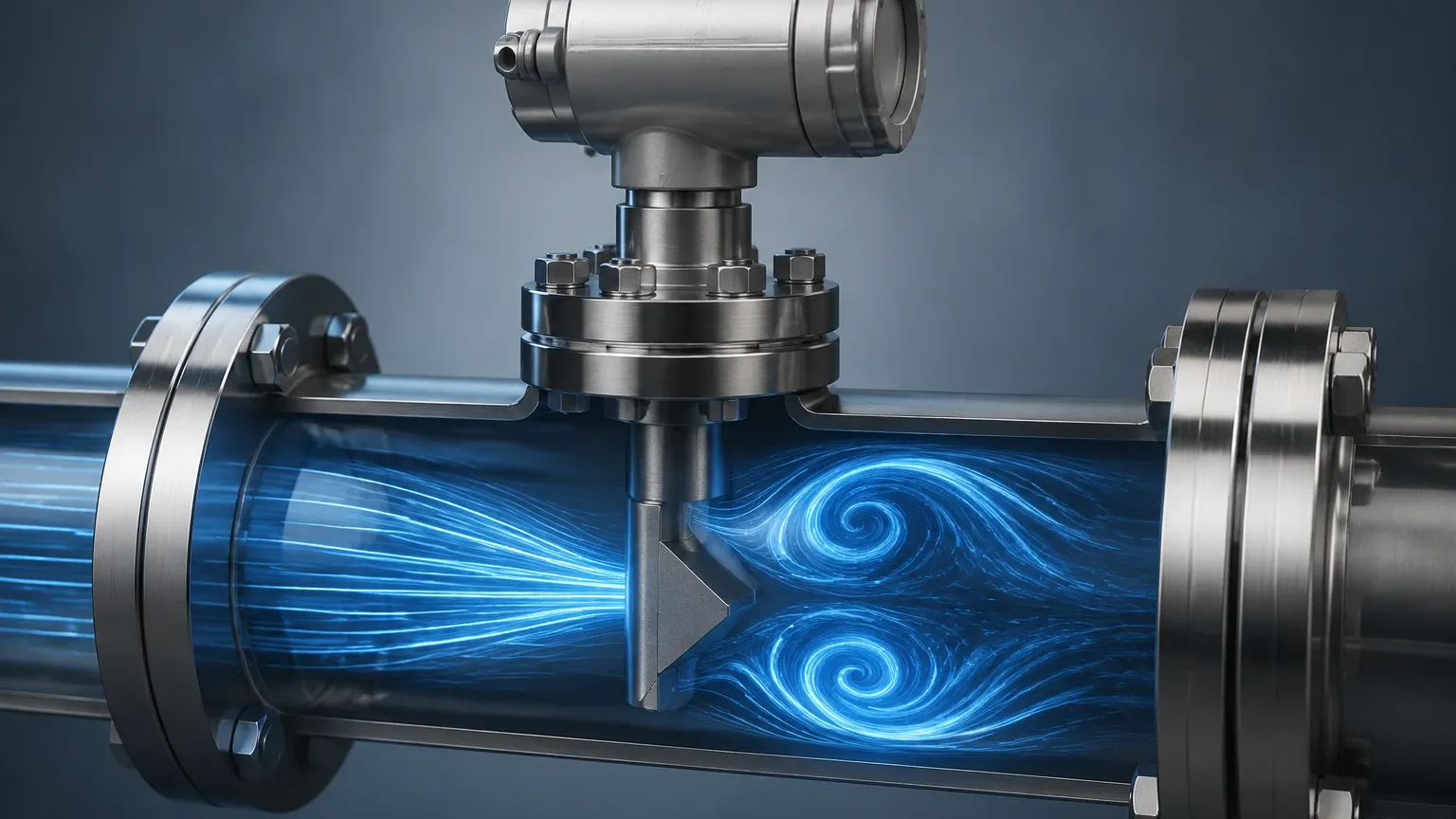
The core of vortex flow meter working is based on a fluid dynamics phenomenon known as the von Kármán effect, named after the Hungarian-American physicist Theodore von Kármán. This principle describes the periodic shedding of vortices (swirls of fluid) that occurs when a fluid flows past a non-streamlined object, often referred to as a "bluff body" or "shedder bar."
The Mechanism of Vortex Generation
As fluid moves through the meter body and encounters the shedder bar, it is unable to follow the sharp contours of the object. This causes the fluid layers to separate and roll up into alternating vortices on either side of the bar. These vortices detach from the bar and move downstream, forming a pattern known as a "vortex street."
The frequency at which these vortices are shed is directly proportional to the velocity of the fluid moving through the pipe. This relationship is expressed by the following formula:
f = St × (V / d)
Where:
* f is the frequency of vortex shedding (Hz).
* St is the Strouhal number (a dimensionless constant specific to the shedder bar geometry).
* V is the flow velocity (m/s).
* d is the width of the shedder bar (m).
Because the Strouhal number remains constant over a wide range of Reynolds numbers, the vortex frequency is linearly proportional to the flow velocity. This linearity is one of the primary advantages of vortex technology, as it allows for accurate measurement across a broad range of flow rates without the need for complex square-root extractions required by differential pressure meters.
Internal Components and Signal Detection
To translate the physical shedding of vortices into a readable electronic signal, a vortex flow meter utilizes several critical components. The quality of these components determines the meter's sensitivity and its ability to operate in harsh industrial environments.
1. The Shedder Bar
The shedder bar is the only stationary part within the flow stream. It is typically constructed from high-grade stainless steel or specialized alloys to resist corrosion and erosion. Its shape is precision-engineered to ensure stable vortex shedding across the widest possible range of flow velocities.
2. The Sensor Element
As vortices pass the shedder bar, they create alternating low-pressure zones. These pressure fluctuations exert a small force on the sensor. Most modern vortex meters, including those offered by Welk, utilize piezoelectric crystals or ultrasonic sensors to detect these pulses.
* Piezoelectric Sensors: These sensors convert mechanical stress from the pressure pulses into electrical charges. They are robust and can withstand the high temperatures often found in steam applications.
* Ultrasonic Sensors: These detect the vortices by measuring the shift in ultrasonic waves as they pass through the vortex street. This method is highly sensitive and can detect lower flow velocities than traditional piezoelectric designs.
3. The Transmitter and Signal Processor
The raw signal from the sensor is often weak and accompanied by process noise (such as pipe vibration). The transmitter’s role is to filter out this noise, amplify the signal, and convert the frequency into a standard industrial output, such as 4-20mA, pulse, or digital protocols like HART, Modbus, or Foundation Fieldbus. For comprehensive system overviews and technical documentation, engineers can refer to the Main Page of our industrial instrument resource.
Technical Specifications and Selection Criteria
Selecting the right vortex flow meter requires a deep understanding of the process fluid and the environmental conditions. Unlike simple level switches, flow meters must account for the dynamic behavior of the fluid.
Fluid Phase and Properties
Vortex meters are "all-rounders" capable of measuring:
* Liquids: Water, chemicals, and light hydrocarbons.
* Gases: Compressed air, nitrogen, and natural gas.
* Steam: Both saturated and superheated steam.
Reynolds Number Requirements
For the vortex flow meter working principle to remain accurate, the flow must be turbulent. This is defined by the Reynolds number ($Re$). Typically, a vortex meter requires a Reynolds number greater than 10,000 to 20,000 to maintain its specified linearity. If the $Re$ drops below this threshold (laminar or transitional flow), the Strouhal number is no longer constant, and the meter's accuracy degrades significantly.
Practical Selection Table
| Parameter | Requirement/Range | Notes |
| :— | :— | :— |
| Fluid Velocity (Liquid) | 0.3 m/s to 7 m/s | Higher velocities risk cavitation. |
| Fluid Velocity (Gas/Steam) | 3 m/s to 80 m/s | Lower densities require higher velocities for detection. |
| Temperature Range | -200°C to +400°C | Cryogenic and high-temp steam versions available. |
| Pressure Rating | Up to 25 MPa (250 bar) | Dependent on flange rating and body material. |
| Accuracy (Liquid) | ±0.75% to ±1.0% | Percentage of actual flow rate. |
| Accuracy (Gas/Steam) | ±1.0% to ±1.5% | Requires pressure/temperature compensation for mass flow. |
Critical Installation Guidelines for Accuracy
The accuracy of a vortex flow meter is highly dependent on the flow profile being fully developed and symmetrical when it reaches the shedder bar. Distorted flow profiles caused by elbows, valves, or reducers will result in measurement errors.
Straight Pipe Runs
To ensure a stable vortex street, the following minimum straight pipe lengths are generally recommended:
* Upstream of the meter: 10 to 20 pipe diameters (D).
* Downstream of the meter: 5 pipe diameters (D).
If a control valve is located upstream, the requirement may increase to 30D or more. In space-constrained environments, flow straighteners or conditioners can be used to reduce these requirements.
Piping and Alignment
* Concentricity: The meter must be perfectly aligned with the pipe centerline. Gaskets should not protrude into the flow stream, as this creates parasitic vortices that interfere with the primary measurement.
* Vibration Mitigation: While modern digital signal processing (DSP) can filter out some mechanical noise, excessive pipe vibration can still cause "false" flow readings at zero flow. Supporting the pipe near the meter is a best practice.
Orientation
* Liquid Service: The pipe must always be full. Vertical upward flow is preferred to ensure no air pockets exist.
* Gas/Steam Service: Horizontal or vertical flow is acceptable, but for steam, the meter should be installed to prevent condensate buildup around the sensor.
Limitations and Operational Constraints
While highly effective, the vortex flow meter is not a universal solution. Engineers must be aware of its specific limitations:
1. Low Flow Cutoff: Because a minimum velocity is required to generate detectable vortices, these meters cannot measure "zero" flow or very slow leaks. Below the cutoff point, the output will drop to zero.
2. Pressure Drop: The shedder bar acts as a permanent restriction in the pipe, causing a permanent pressure loss. This must be accounted for in the system's hydraulic calculations.
3. Cavitation Risk: In liquid applications, the low-pressure zone behind the shedder bar can cause the liquid to flash into vapor (cavitation) if the process pressure is too low. This damages the sensor and causes erratic readings.
4. Multi-phase Flow: Vortex meters are designed for single-phase fluids. The presence of significant solids, large bubbles in liquids, or excessive moisture in gases will disrupt vortex formation.
Comparative Analysis: Vortex vs. Differential Pressure Meters
| Feature | Vortex Flow Meter | Orifice Plate (DP) |
| :— | :— | :— |
| Turndown Ratio | High (up to 20:1) | Low (typically 4:1) |
| Accuracy | High (Linear) | Medium (Non-linear) |
| Maintenance | Low (No moving parts) | High (Orifice wear/clogging) |
| Installation Cost | Moderate | High (Impulse lines required) |
| Pressure Loss | Moderate | High |
Compared to traditional orifice plates, vortex meters offer a wider turndown ratio and lower maintenance costs because they do not rely on impulse lines that can freeze or leak. However, for very large pipe diameters (above 300mm), the cost of a full-bore vortex meter can become prohibitive, making insertion-type vortex meters or DP systems more economical.
Frequently Asked Questions (FAQs)
Q: Can a vortex flow meter measure mass flow?
A: Standard vortex meters measure volumetric flow. However, "multivariable" vortex meters include integrated temperature and pressure sensors. By using the fluid's equation of state, the transmitter can calculate the real-time density and provide a mass flow output, which is particularly useful for steam applications.
Q: How does viscosity affect the measurement?
A: As viscosity increases, the Reynolds number decreases. If the fluid is too viscous (typically above 10-20 centipoise), the vortices become too weak to detect. Vortex meters are generally best suited for low-viscosity fluids.
Q: Is periodic recalibration necessary?
A: Because the vortex shedding frequency depends only on the geometry of the shedder bar, which does not change over time (unless eroded), the meter's K-factor is exceptionally stable. Periodic verification of the electronics is recommended, but full wet calibration is rarely needed unless the shedder bar is physically damaged.
Conclusion
The success of vortex flow meter working in industrial environments stems from its elegant application of fluid dynamics. By converting the frequency of physical vortices into precise digital data, these instruments provide the reliability needed for modern process automation. Whether managing steam in a chemical plant or monitoring compressed air in a manufacturing facility, understanding the selection and installation nuances ensures long-term accuracy. For those seeking to integrate these sensors with broader level and flow management systems, exploring the Main Page of Welk’s technical resources provides the necessary foundation for informed procurement and engineering decisions.