Metering Skid Oil and Gas
Metering Skid Oil and Gas
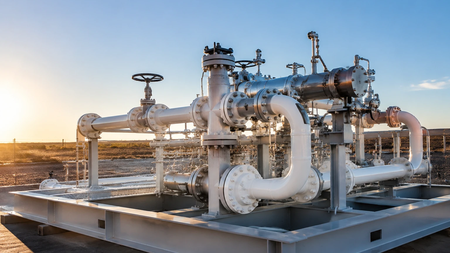
In the global energy sector, accuracy is the cornerstone of commercial viability. A metering skid oil and gas system serves as the primary gateway for the measurement of hydrocarbons during production, transport, and distribution. These modular, pre-assembled units are engineered to provide precise data on the volume and quality of oil, gas, or refined products. Because these measurements often dictate the financial value of a transaction—a process known as custody transfer—the reliability of the instrumentation within the skid is paramount.
A metering skid is more than a simple flow meter; it is a complex integration of piping, valves, filtration systems, and sophisticated instrumentation. This guide explores the technical foundations of these systems, focusing on the measurement principles that ensure operational integrity and fiscal accuracy.
Understanding the Role of Metering Skids
A metering skid oil and gas application typically involves the transfer of fluids between two parties, such as a producer and a pipeline operator, or a refinery and a distribution terminal. The primary objective is to provide a "fiscal" grade measurement that meets international standards (such as API or OIML).
Beyond simple volume measurement, these skids often perform secondary functions, including:
- Pressure and Temperature Compensation: Adjusting raw volume data to standard conditions.
- Quality Analysis: Using densitometers or sampling systems to determine the composition of the fluid.
- Flow Conditioning: Removing turbulence to ensure the flow meter operates within its calibrated range.
- Level Monitoring: Managing surge tanks or separators integrated into the skid to prevent gas carry-under or liquid carry-over.
For engineers designing these systems, selecting the right level and flow measurement technologies is the first step toward a high-performance installation. You can explore a wide range of industrial sensors and instrumentation on our Main Page.
Core Measurement Principles
Before selecting specific hardware for a metering skid oil and gas project, it is essential to understand the physics behind the measurement. In the context of level measurement—which is critical for the storage tanks and separators often found on these skids—three primary principles dominate the industry.
1. Radar Level Measurement (ToF)
Radar level meters operate on the Time-of-Flight (ToF) principle. The device emits a high-frequency electromagnetic pulse (usually in the GHz range) toward the surface of the liquid. The pulse reflects off the surface and returns to the sensor. By measuring the time it takes for the signal to travel to the surface and back, the device calculates the distance based on the speed of light.
- Non-Contact Radar: Ideal for corrosive or volatile hydrocarbons as the sensor does not touch the media.
- Guided Wave Radar (GWR): Uses a probe to guide the signal, making it highly effective in low-dielectric fluids or environments with heavy foam.
2. Ultrasonic Level Measurement
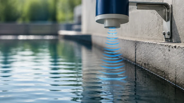
Similar to radar, ultrasonic sensors use ToF, but they employ sound waves instead of electromagnetic waves. The sensor emits an ultrasonic pulse that reflects off the liquid surface. While cost-effective, ultrasonic measurement is sensitive to air temperature, pressure changes, and the presence of heavy vapors or dust, which can attenuate the sound signal.
3. Hydrostatic Pressure Measurement
This principle relies on the relationship between the height of a liquid column and the pressure it exerts at the base. By measuring the head pressure (P) and knowing the density of the fluid (ρ) and the force of gravity (g), the level (h) can be calculated using the formula: $h = P / (ρ \cdot g)$. This method is robust but requires accurate density data, which can fluctuate in oil and gas applications.
Level Measurement Technologies for Metering Skids
While flow meters (Coriolis, Ultrasonic, or Turbine) are the heart of the skid, level sensors provide the necessary oversight for auxiliary vessels. These vessels, such as knock-out drums or calibration tanks, ensure that the flow entering the primary meters is stable and single-phase.
| Technology | Typical Accuracy | Best Use Case | Limitations |
| :— | :— | :— | :— |
| Guided Wave Radar | ±2 mm | Low dielectric liquids, interface measurement | Physical probe may accumulate paraffin |
| Non-Contact Radar | ±1 mm to ±5 mm | Large storage tanks, corrosive crude oil | Requires clear line of sight |
| Ultrasonic | ±0.25% of range | Water treatment, atmospheric tanks | Not suitable for high pressure or vacuum |
| Hydrostatic | ±0.1% to ±0.5% | Constant density liquids, deep tanks | Density changes affect accuracy |
| Magnetic Gauges | Visual + ±5 mm | High-pressure separators, toxic fluids | Mechanical parts can wear over time |
Selection Criteria for Metering Skid Instrumentation
Choosing the correct instrumentation for a metering skid oil and gas project requires a multi-faceted evaluation. Engineers must balance accuracy requirements with the harsh realities of the field environment.
Fluid Properties
The chemical composition of the hydrocarbon is the most significant factor. For example, crude oil with high sulfur content (sour crude) requires sensors made from corrosion-resistant alloys like Hastelloy or Monel. If the fluid has a low dielectric constant (typical of many refined oils), Guided Wave Radar is often preferred over non-contact radar to ensure a strong signal return.
Process Conditions
- Pressure: Metering skids in midstream applications often operate at high pressures (e.g., ANSI 600 or 900). Sensors must be rated for these pressures with appropriate flange connections.
- Temperature: Extreme temperatures can affect sensor electronics. In cold climates, heat tracing may be required; in high-temperature applications, cooling fins or remote electronics are necessary.
Regulatory and Fiscal Standards
For custody transfer, the instrumentation must comply with local and international weights and measures regulations. This often involves specific redundancy requirements, such as using two different measurement technologies to cross-verify data.
Installation and Engineering Best Practices
Even the most advanced sensor will fail to provide accurate data if installed incorrectly. For a metering skid oil and gas system, the following installation guidelines are critical:
1. Nozzle Positioning: For radar and ultrasonic sensors, the mounting nozzle should be located away from the tank wall to avoid false reflections (parasitic echoes). It should also be positioned away from the inlet pipe to prevent the liquid stream from interfering with the signal.
2. Stilling Wells: In tanks with significant turbulence or foam, installing the level sensor inside a stilling well (a perforated pipe) can provide a calm surface for measurement, significantly increasing accuracy.
3. Grounding and Shielding: Oil and gas environments are prone to electromagnetic interference (EMI) from pumps and motors. Proper grounding of instrument housings and the use of shielded cables are essential to prevent signal noise.
4. Calibration Access: Skids should be designed with enough space for technicians to perform routine calibration and maintenance. This includes the installation of bypass valves and isolation manifolds for pressure and level transmitters.
Maintenance and Risk Mitigation
The primary risk in a metering skid oil and gas operation is "measurement uncertainty." Small errors in measurement can result in significant financial losses over time. Regular maintenance schedules should include:
- Verification of Zero and Span: Periodically checking that the sensor reads correctly at empty and full states.
- Cleaning of Probes: In heavy oil applications, paraffin or bitumen can build up on radar probes or ultrasonic transducers, leading to signal loss.
- Diagnostic Monitoring: Modern digital instruments (using HART, Modbus, or Foundation Fieldbus) provide internal diagnostics that can predict failure before it occurs, such as detecting a weakening signal or a fouled sensor face.
Frequently Asked Questions (FAQ)
Q: Why is radar preferred over ultrasonic for oil and gas skids?
A: Radar waves are electromagnetic and do not require a medium (air) to travel. They are unaffected by the vapors, high pressures, and temperature fluctuations common in hydrocarbon tanks, whereas ultrasonic sound waves are highly sensitive to these factors.
Q: Can one skid handle both oil and gas?
A: Generally, no. The physical properties of liquids and gases require different flow meter types (e.g., Coriolis for liquids and Ultrasonic or Orifice for gases) and different piping configurations. However, "multiphase" skids exist for wellhead testing, though they are more complex and less accurate than single-phase metering skids.
Q: What is the significance of the "dead zone" in level measurement?
A: The dead zone (or blocking distance) is the area directly below the sensor where it cannot take a measurement. When designing a metering skid tank, the maximum liquid level must be kept below this zone to prevent measurement errors.
Q: How often should a metering skid be calibrated?
A: This is usually determined by the contract between the buyer and seller or by local regulations. In many custody transfer applications, calibration (or "proving") is performed monthly or even per-batch.
Conclusion
A metering skid oil and gas system is a critical asset that demands high-precision engineering and robust instrumentation. By understanding the underlying measurement principles—from the time-of-flight of radar pulses to the physics of hydrostatic pressure—operators can ensure their systems remain accurate, compliant, and profitable.
Whether you are upgrading an existing facility or designing a new modular skid, selecting the right level measurement technology is vital for long-term success. For detailed product specifications and technical support for your next project, please visit our Main Page.