Px3ulx05
Px3ulx05
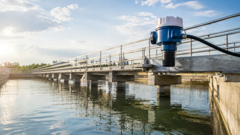
In the landscape of industrial automation, precise level measurement is a cornerstone of operational efficiency and safety. The px3ulx05 refers to a specific configuration within the family of ultrasonic level transmitters, designed to provide non-contact measurement for liquids and certain solids. As process industries move toward higher levels of integration and real-time monitoring, understanding the technical nuances of instruments like the px3ulx05 becomes essential for instrumentation engineers and plant managers.
This article provides a comprehensive technical overview of the px3ulx05, detailing its underlying measurement principles, selection criteria, installation requirements, and common industrial applications. By adhering to established engineering standards, this guide serves as a reference for integrating these sensors into modern control systems.
Understanding the Measurement Principle of Ultrasonic Level Transmitters
Before evaluating the specific capabilities of the px3ulx05, it is necessary to understand the physics of ultrasonic level measurement. These instruments operate on the "Time of Flight" (ToF) principle.
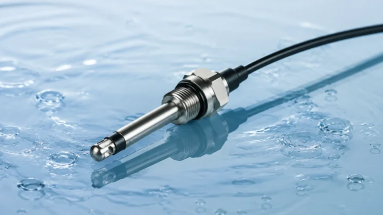
An ultrasonic sensor, such as the px3ulx05, contains a piezoelectric transducer that converts electrical energy into mechanical vibrations. These vibrations create high-frequency sound waves (ultrasonic pulses) that are emitted toward the target medium. When these waves strike the surface of the liquid or solid, they are reflected back toward the sensor. The sensor then reverts to a receiving mode to capture the returning echo.
The Calculation of Distance
The internal microprocessor of the instrument calculates the distance between the sensor face and the material surface using the following formula:
Distance = (Speed of Sound × Time Delay) / 2
Because the speed of sound in air is approximately 340 meters per second (at 20°C), the instrument can determine the level with high precision by measuring the nanosecond intervals between pulse emission and echo reception. To provide a true level reading (the height of the material), the user must program the "Empty Distance" (the total height from the sensor face to the bottom of the tank). The level is then calculated as:
Level = Empty Distance – Measured Distance
Temperature Compensation
A critical factor in ultrasonic measurement is that the speed of sound changes with air temperature. A variation of 1°C can result in a 0.17% error in distance measurement. Professional-grade sensors like the px3ulx05 incorporate an integrated temperature thermistor. This component continuously monitors the ambient temperature within the sensor housing and automatically adjusts the calculation to maintain accuracy across varying environmental conditions.
Technical Characteristics of the px3ulx05 Series
The px3ulx05 is typically categorized as a short-to-medium range ultrasonic transmitter. The "05" designation often signifies a maximum effective measuring range of 5 meters (approximately 16.4 feet). This makes it an ideal candidate for small-to-medium storage tanks, sumps, and open-channel flow applications.
Key Specifications
1. Measuring Range: 0.25m to 5.0m. The lower limit (0.25m) represents the "Dead Zone" or blocking distance, where the sensor cannot accurately process echoes due to the time required for the transducer to stop vibrating after emission.
2. Output Signals: Most units provide a standard 4-20mA analog output, which is compatible with PLCs (Programmable Logic Controllers) and DCS (Distributed Control Systems). Digital communication options often include RS485 Modbus or HART protocols.
3. Accuracy: Typically ±0.25% to ±0.5% of the full measuring range, providing reliable data for inventory management.
4. Ingress Protection: These sensors are usually rated IP67 or IP68, ensuring they are dust-tight and protected against moisture ingress, which is common in wastewater and chemical processing environments.
5. Power Supply: Available in 2-wire (loop-powered) or 4-wire configurations, depending on the power requirements of the specific application and the complexity of the signal processing required.
For engineers looking to integrate these devices into larger systems, the Main Page of the manufacturer provides detailed wiring diagrams and protocol documentation.
Application Suitability and Selection Criteria
Choosing the px3ulx05 requires an analysis of the process environment. While ultrasonic technology is versatile, it is not a universal solution.
Ideal Applications
* Water and Wastewater Treatment: Monitoring levels in wet wells, chemical dosing tanks, and effluent channels. Since the sensor does not touch the liquid, it is immune to the corrosive or fouling nature of sewage.
* Chemical Storage: Suitable for acids, alkalis, and other corrosive liquids, provided the sensor face material (usually PVDF or PTFE) is chemically compatible with the vapors.
* Food and Beverage: Non-contact measurement ensures that there is no risk of contamination to the product.
* Open Channel Flow: When paired with a flume or weir, the px3ulx05 can calculate flow rates based on the head level of the water.
Selection Table: Ultrasonic vs. Alternative Technologies
| Feature | px3ulx05 (Ultrasonic) | Radar Level Meter | Hydrostatic Transmitter |
| :— | :— | :— | :— |
| Contact Type | Non-contact | Non-contact | Contact (Submerged) |
| Medium | Liquids / Some Solids | Liquids / Solids | Liquids only |
| Pressure Limit | Near Atmospheric | High Pressure | High Pressure |
| Vacuum Suitability| Poor (No sound travel) | Excellent | Good |
| Cost | Cost-effective | Higher | Moderate |
| Installation | Top-mounted | Top-mounted | Side or Bottom-mounted |
Critical Installation Guidelines for px3ulx05 Sensors
Correct installation is the most significant factor in the performance of an ultrasonic level meter. Poor placement can result in signal loss, false echoes, or erratic readings.
1. The Dead Zone (Blocking Distance)
As mentioned previously, the px3ulx05 has a dead zone of approximately 0.25m to 0.3m. The sensor must be mounted such that the highest possible liquid level never enters this zone. If the liquid reaches the dead zone, the sensor may report a full tank as empty or provide a fixed, incorrect value.
2. Beam Angle and Obstructions
The ultrasonic pulse spreads out in a cone shape, typically with a beam angle between 5° and 12°. It is vital to ensure that no internal tank structures—such as ladders, heating coils, or pipes—interrupt this beam. If an obstruction is unavoidable, many px3ulx05 units offer "False Echo Suppression" software, allowing the user to program the sensor to ignore specific reflections at known distances.
3. Orientation and Positioning
* Perpendicularity: The sensor face must be perfectly parallel to the liquid surface. A tilt of even a few degrees can cause the reflected signal to miss the transducer entirely.
* Wall Distance: The sensor should not be mounted too close to the tank wall. A general rule is to maintain a distance from the wall equal to at least 1/10th of the tank height to prevent side-wall interference.
* Inlet Avoidance: Never install the sensor directly above the tank inlet. The turbulence and splashing from incoming liquid will scatter the ultrasonic signal and create significant noise.

Challenges and Environmental Limitations
While the px3ulx05 is a robust instrument, certain process conditions can hinder its accuracy or prevent it from functioning altogether.
Foam and Turbulence
Heavy foam on the surface of a liquid acts as an acoustic absorber. Instead of reflecting the ultrasonic pulse, the foam dissipates the energy, leading to a "Lost Echo" error. In cases of light foam, the sensor may still function, but with reduced signal strength. Similarly, extreme surface turbulence can scatter the signal. In these scenarios, a stilling well (a vertical pipe that stabilizes the liquid surface) is often recommended.
Vacuum and High Pressure
Ultrasonic waves require a medium (air or gas) to travel. Therefore, the px3ulx05 cannot function in a vacuum. Furthermore, high-pressure environments change the density of the air, which significantly alters the speed of sound beyond the compensation capabilities of standard sensors. For vacuum or high-pressure applications, radar level meters are generally the preferred choice.
Dust and Vapors
Heavy dust in the air (common in grain silos) or dense steam/vapors can attenuate the ultrasonic signal. While the px3ulx05 can handle moderate vapor, applications involving boiling liquids or thick chemical fumes may require a higher-power transducer or a transition to radar technology.
Maintenance and Troubleshooting for Industrial Level Meters
One of the primary advantages of the px3ulx05 is its low maintenance requirement, stemming from its non-contact design. However, periodic checks are necessary to ensure long-term reliability.
Routine Inspection
* Transducer Cleaning: In humid or dusty environments, condensation or buildup can occur on the sensor face. This should be cleaned gently with a soft cloth and water or a mild detergent. Avoid abrasive materials that could scratch the transducer surface.
* Cable Integrity: Check the cable glands and housing seals for signs of wear or moisture ingress. Ensure that the vent (if present) is not blocked, as this allows the sensor to equalize pressure.
Common Troubleshooting Steps
1. Reading is Fixed at Maximum: This often indicates that the sensor has lost its echo. Check for foam, extreme turbulence, or if the sensor has been tilted.
2. Reading Jumps Erratically: This is usually caused by electrical interference or internal tank obstructions. Ensure the signal cable is shielded and grounded at one end, and check for pipes or ladders within the beam path.
3. Reading is Incorrect by a Constant Offset: This typically points to an error in the "Empty Distance" or "Offset" settings in the device configuration.
Frequently Asked Questions (FAQs)
Q: Can the px3ulx05 be used for solids like sand or grain?
A: Yes, but the range is significantly reduced. Solids do not reflect sound as efficiently as liquids and often have an angle of repose that deflects the signal. For solids, it is recommended to de-rate the sensor's maximum range by 50%.
Q: What is the maximum cable length for the 4-20mA signal?
A: For a standard 4-20mA loop, the cable can typically run up to 1,000 meters, depending on the wire gauge and the power supply voltage, provided there is adequate shielding to prevent EMI.
Q: Does the px3ulx05 work in outdoor tanks during winter?
A: Yes, provided the temperature remains within the specified operating range (usually -20°C to +60°C). However, heavy ice buildup on the sensor face will prevent measurement.
Q: How do I calibrate the px3ulx05?
A: Most modern units are "calibrated" via software by entering the tank dimensions (Height and Dead Zone). A physical calibration with a reference level is recommended during commissioning to verify accuracy.
For further technical support and to explore the full range of available measurement technologies, engineers are encouraged to consult the Main Page for updated product manuals and application notes. Selecting the right instrument involves balancing the physical constraints of the process with the required precision, and the px3ulx05 remains a reliable standard for many industrial level sensing needs.