Micro Motion Flow Meters
Micro Motion Flow Meters
In the landscape of industrial process control, the ability to measure fluid movement with high precision is fundamental to operational efficiency, safety, and fiscal accountability. Among the various technologies available, micro motion flow meters—specifically those utilizing the Coriolis principle—stand as the benchmark for accuracy and reliability. These instruments are unique because they measure mass flow directly, rather than inferring it from volume or velocity, making them indispensable in sectors ranging from chemical processing to oil and gas.
For engineers and project managers, understanding the nuances of these meters is essential for selecting the right instrumentation. This guide explores the technical principles, selection criteria, and practical application of Coriolis technology within a modern industrial framework.
Understanding the Coriolis Measurement Principle
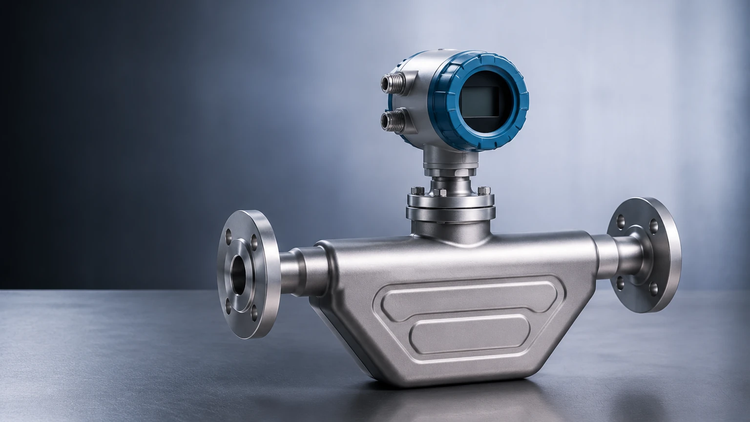
The fundamental operation of micro motion flow meters relies on the Coriolis effect. To understand this in an industrial context, one must look at the internal architecture of the meter, which typically consists of one or two vibrating tubes.
The Physics of Mass Flow
An internal drive coil causes the sensing tubes to oscillate at their natural resonant frequency. When a fluid (liquid or gas) is at rest within the tubes, the tubes vibrate in a uniform, symmetrical manner. However, once the fluid begins to flow, the Coriolis force is generated. This force acts in opposition to the oscillation, causing the tubes to twist or experience a "phase shift."
Electromagnetic sensors (pickoffs) located at the inlet and outlet sides of the tubes measure this shift. The time delay between the signals from these two sensors is directly proportional to the mass flow rate. Because mass does not change with variations in temperature or pressure, this measurement is inherently more stable than volumetric methods.
Density and Temperature Measurement
Beyond mass flow, micro motion flow meters are multivariable instruments. The density of the fluid is determined by measuring the resonant frequency of the tube vibration. A denser fluid increases the mass of the vibrating system, thereby lowering the frequency. Simultaneously, an integrated Resistance Temperature Detector (RTD) monitors the tube temperature to compensate for changes in material elasticity, providing a third data point. This combination allows for the calculation of volume flow and concentration in real-time.
Key Technical Specifications and Evaluation Criteria
When evaluating micro motion flow meters for a specific project, several technical parameters dictate the performance and suitability of the device. Engineers must look beyond the basic flow range to ensure the meter can handle the specific dynamics of the process.
Accuracy and Repeatability
One of the primary reasons for selecting Coriolis technology is its superior accuracy. High-end models typically offer mass flow accuracy of ±0.05% to ±0.1% for liquids and ±0.25% to ±0.5% for gases. Repeatability is often even tighter, ensuring that the process remains consistent over thousands of cycles.
Turndown Ratio
The turndown ratio, or rangeability, refers to the ratio between the maximum and minimum flow rates the meter can measure within its specified accuracy. Micro motion flow meters often feature turndown ratios of 20:1 or even 100:1. This is critical in applications where flow rates vary significantly during different phases of production.
Material Compatibility
The wetted parts of the meter—the components that come into direct contact with the fluid—must be resistant to corrosion and erosion. Common materials include 316L Stainless Steel, Nickel alloys (such as Hastelloy C-22), and Tantalum for highly aggressive chemical environments. Selecting the wrong material can lead to tube failure, which is a significant safety risk in high-pressure systems.
Industrial Applications and Integration
Micro motion flow meters are utilized where precision is non-negotiable. Their ability to handle complex fluids makes them a staple in modern automation.
* Chemical Processing: Used for precise dosing of catalysts and reactants. The density measurement capability allows for real-time monitoring of chemical concentrations, reducing the need for manual sampling.
* Oil and Gas: Essential for custody transfer and fiscal metering. Since the meter measures mass, it eliminates the errors associated with the compressibility of hydrocarbons under varying pressures.
* Water Treatment: While often monitored by level instruments, flow meters are used in the precise injection of treatment chemicals and the monitoring of effluent discharge.
In many of these environments, flow measurement is paired with level measurement to provide a complete picture of vessel inventory. For those managing complex tank farms or processing units, reviewing comprehensive Main Page resources on level and flow integration is a recommended step in system design.
Practical Selection Table for Process Engineers
The following table provides a general guideline for selecting meter sizes based on typical flow ranges and common industrial requirements.
| Meter Size (DN) | Nominal Flow Rate (kg/h) | Max Pressure (bar) | Typical Application |
| :— | :— | :— | :— |
| DN15 (1/2") | 500 – 6,000 | 100 – 300 | Chemical dosing, pilot plants |
| DN25 (1") | 2,000 – 20,000 | 100 – 250 | Batching, additive injection |
| DN50 (2") | 10,000 – 70,000 | 60 – 150 | Loading racks, fuel monitoring |
| DN80 (3") | 30,000 – 180,000 | 40 – 100 | Bulk transfer, main process lines |
| DN100 (4") | 50,000 – 300,000 | 40 – 100 | Custody transfer, large scale distribution |
*Note: Flow rates are indicative and vary based on fluid viscosity and allowable pressure drop.*
Installation Best Practices and Maintenance
Even the most accurate micro motion flow meter will underperform if installed incorrectly. Because the device relies on delicate vibrations, external factors can introduce noise into the signal.
Orientation and Support
For liquid applications, the meter should ideally be installed with the tubes pointing downward ("flag" or "U" down) to prevent the accumulation of air bubbles. For gas applications, the tubes should point upward to prevent condensate from pooling. The meter must be supported by the pipeline itself, and the piping should be anchored near the meter inlets and outlets to isolate it from external vibrations.
Zero Verification
Upon installation and under full-pipe, zero-flow conditions, a "zero calibration" must be performed. This accounts for the specific mechanical stresses of the piping installation. Regular zero verification is a standard maintenance task to ensure long-term accuracy.
Avoiding Cavitation and Flashing
To maintain measurement integrity, the fluid must remain in a single phase. If the pressure drops too low, the liquid may vaporize (flashing) or form bubbles (cavitation). This disrupts the vibration of the tubes and can lead to "slug flow" errors. Ensuring sufficient backpressure is a critical design consideration.
Limitations and Common Operational Risks
While highly versatile, micro motion flow meters are not a universal solution for every scenario. Understanding their limitations prevents costly procurement errors.
1. Initial Capital Cost: Coriolis meters are generally more expensive than electromagnetic or vortex meters. The investment is usually justified by the reduction in maintenance and the high accuracy, but it may be prohibitive for simple water-monitoring tasks.
2. Pressure Drop: The geometry of the vibrating tubes (especially U-shaped designs) can introduce a significant pressure drop in the system. This must be calculated during the pump sizing phase.
3. Entrained Gas: While modern digital signal processing has improved the ability of meters to handle "two-phase flow," excessive air or gas in a liquid stream can still cause the meter to stall or provide inaccurate readings.
4. Size and Weight: Large Coriolis meters (above DN200) are exceptionally heavy and bulky, requiring specialized mounting structures and significant space.
Frequently Asked Questions
Q: Can micro motion flow meters measure non-conductive liquids?
Yes. Unlike electromagnetic flow meters, which require a conductive fluid, Coriolis meters are unaffected by the electrical properties of the medium. They work equally well with deionized water, hydrocarbons, and pure chemicals.
Q: How does viscosity affect the measurement?
Coriolis meters are largely independent of viscosity. However, very high-viscosity fluids will result in a higher pressure drop across the meter, which may require a larger meter size or increased pumping power.
Q: Is straight-run piping required before and after the meter?
One of the major advantages of micro motion flow meters is that they generally do not require the long straight-run piping (upstream and downstream) that turbine or orifice plate meters require. This makes them ideal for compact skids and tight installations.
Q: What is the typical lifespan of these instruments?
In non-corrosive and non-erosive service, a Coriolis meter can last 20 years or more. Because there are no moving parts like bearings or gears, mechanical wear is virtually non-existent.
Conclusion
Micro motion flow meters represent the pinnacle of mass flow technology, offering a level of data depth—mass, density, and temperature—that few other instruments can match. By understanding the Coriolis principle and adhering to strict installation standards, industrial operators can achieve unparalleled process control. When specifying these units, it is vital to confirm fluid properties, pressure constraints, and integration requirements with a qualified instrumentation partner to ensure the selected solution meets the long-term needs of the facility.