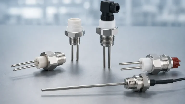
Micropilot Fmr245
Micropilot Fmr245
In the realm of industrial process automation, achieving precise level measurement in challenging environments is a fundamental requirement for operational safety and efficiency. The Micropilot FMR245 is a high-frequency radar level sensor designed specifically for continuous, non-contact level measurement in aggressive liquids or applications with high hygiene requirements. This article provides a technical exploration of the principles behind radar level measurement, the specific capabilities of the FMR245, and the critical engineering considerations required for successful deployment.
Understanding Radar Level Measurement Principles
Before evaluating specific hardware like the Micropilot FMR245, it is essential to understand the underlying physics of radar technology in industrial settings. Radar level meters operate on the "Time of Flight" (ToF) principle.
The Time of Flight (ToF) Method
Radar sensors emit high-frequency electromagnetic pulses (typically in the GHz range) toward the surface of the medium. These pulses travel at the speed of light. When the signal encounters a change in the dielectric constant (the boundary between air and the process medium), a portion of the energy is reflected back to the sensor antenna. The instrument measures the time elapsed between the emission of the pulse and the reception of the echo.
Since the speed of light is a known constant, the distance ($D$) to the surface is calculated as:
$D = (c \times t) / 2$
Where $c$ is the speed of light and $t$ is the measured time. The actual level ($L$) is then determined by subtracting this distance from the total height of the vessel ($H$).
Frequency and Beam Angle
The Micropilot FMR245 operates at a frequency of approximately 26 GHz (K-band). Frequency is a decisive factor in radar performance for two reasons:
1. Beam Focusing: Higher frequencies allow for smaller antenna sizes while maintaining a narrow beam angle. A 26 GHz radar can achieve a beam angle as narrow as 8° to 10° with a standard horn antenna, which is significantly better than the 20° to 30° angles typical of 6 GHz sensors.
2. Sensitivity: Higher frequencies are generally more sensitive to reflections from small-scale surface turbulence, though they may be more susceptible to attenuation from heavy steam or dust.
For engineers seeking to compare these principles across different hardware configurations, the Main Page of our technical resource center provides a detailed breakdown of how frequency affects signal reliability in various tank geometries.
Technical Overview of the Micropilot FMR245
The Micropilot FMR245 is engineered for applications where chemical resistance and precision are paramount. It is frequently utilized in the chemical and pharmaceutical industries due to its specialized antenna designs.
Key Design Features
* Material Compatibility: The sensor often features a completely PTFE-clad antenna or a flush-mounted horn antenna. This ensures that no metallic parts are exposed to corrosive process vapors.
* High Precision: Under reference conditions, the device typically offers an accuracy of ±2 mm (approx. 0.08 inches).
* Pressure and Temperature Range: It is designed to operate in process temperatures ranging from -40 °C to +150 °C and pressures from vacuum up to 16 bar (1.6 MPa).
* Communication: Standard outputs include 4 to 20 mA HART, PROFIBUS PA, or FOUNDATION Fieldbus, allowing for seamless integration into existing Distributed Control Systems (DCS).
Application Suitability
The 26 GHz frequency of the micropilot fmr245 makes it ideal for vessels with internal obstructions. Because the beam is narrow, it can be directed to avoid agitators, heating coils, or support struts that would otherwise cause "false echoes" in lower-frequency systems.
Key Evaluation Criteria for Radar Sensors
When selecting a radar level meter, engineers must look beyond the basic measurement range. The following criteria determine whether a sensor will perform reliably in a specific B2B industrial environment.
Dielectric Constant (εr)
The dielectric constant of the medium is the most critical factor in radar level measurement. It determines how much energy is reflected back to the sensor.
* High εr (>10): Materials like water or aqueous solutions reflect radar waves very well, making measurement straightforward.
* Low εr (1.4 to 4): Hydrocarbons, oils, and some solvents reflect only a small portion of the signal. In these cases, a 26 GHz sensor like the micropilot fmr245 is often preferred because its focused beam concentrates the available energy, improving the signal-to-noise ratio.
Process Dynamics
Is the surface calm, or is there heavy agitation? Turbulence can scatter the radar signal, leading to signal loss. In such cases, software algorithms for echo tracking and signal averaging become essential. Furthermore, the presence of foam can either reflect the signal (if the foam is dense and conductive) or absorb it entirely, leading to measurement failure.
Selection Table for Industrial Level Meters
The following table provides a comparison of common radar configurations used in industrial automation, including the performance envelope of the micropilot fmr245 series.
| Feature | 26 GHz Radar (e.g., FMR245) | 80 GHz Radar | 6 GHz Radar | Guided Wave Radar (GWR) |
| :— | :— | :— | :— | :— |
| Best Use Case | Corrosive liquids, small nozzles | Very small tanks, high precision | Heavy steam, turbulence | Low εr, foam, bypass pipes |
| Max Range | Up to 40m | Up to 100m+ | Up to 30m | Up to 45m |
| Beam Angle | 8° – 12° | 3° – 4° | 20° – 30° | N/A (Signal follows probe) |
| Chemical Resistance | Excellent (PTFE cladding) | Good | Moderate | Depends on probe material |
| Accuracy | ±2 mm | ±1 mm | ±5 mm to ±10 mm | ±2 mm |
| Typical Pressure | Up to 16 bar | Up to 160 bar | Up to 40 bar | Up to 400 bar |

Installation Considerations and Best Practices
Even the most advanced radar sensor will fail if installed incorrectly. For the micropilot fmr245, adherence to geometric constraints is vital for maintaining signal integrity.
Nozzle Geometry
The radar antenna should ideally extend beyond the mounting nozzle. If the antenna is recessed deep within a narrow nozzle, the radar signal will reflect off the nozzle walls, creating a large "ringing" effect near the top of the tank. This is known as the Blocking Distance or Dead Zone.
* Standard Rule: The nozzle height should be kept as short as possible. For the FMR245, if using a horn antenna, the diameter of the nozzle should be at least as large as the horn diameter.
Vessel Placement
* Avoid the Center: Do not install the sensor in the center of a cylindrical tank. This can lead to multiple reflections (parabolic effect) that amplify noise.
* Avoid the Wall: Maintain a minimum distance from the tank wall, typically 1/6th of the tank diameter, to prevent interference from wall seams or buildup.
* Obstructions: Ensure the signal path is clear of ladders, limit switches, or fill streams. If an obstruction is unavoidable, most modern sensors allow for "Fixed Error Mapping," where the software is taught to ignore echoes at specific distances.
Orientation
The sensor should be mounted such that the radar beam is perpendicular to the liquid surface. While a slight tilt might be used in some solid applications to capture the angle of repose, in liquid applications, a perpendicular orientation ensures the maximum reflected energy returns to the receiver.
Common Risks and Limitations in Radar Applications
While the micropilot fmr245 is a robust instrument, certain process conditions present inherent risks to non-contact radar technology.
1. Heavy Foam: Foam is the primary enemy of non-contact radar. Some foams are transparent to radar, while others are totally absorbent. If the process consistently produces thick, dry foam, Guided Wave Radar (GWR) or hydrostatic pressure transmitters may be more reliable alternatives.
2. Condensation and Buildup: In highly humid environments, droplets can form on the antenna. While the FMR245 often uses a "drip-off" PTFE antenna design to mitigate this, extreme buildup of viscous or crystallizing media can eventually attenuate the signal.
3. Vacuum Conditions: While radar works in a vacuum (unlike ultrasonic sensors which require a medium for sound travel), the mechanical seals and flange ratings of the instrument must be verified for vacuum service to prevent air ingress or sensor damage.
4. Multiple Interfaces: Radar primarily measures the top-most surface. If you need to measure the interface between two liquids (e.g., oil and water), Guided Wave Radar is typically required.
Maintenance and Troubleshooting FAQs
Q: How often does the Micropilot FMR245 require calibration?
A: Being a non-contact electronic instrument with no moving parts, the FMR245 does not suffer from mechanical wear. In many stable applications, a verification check once every 12 to 24 months is sufficient. However, regulated industries (like pharmaceuticals) may require more frequent documented calibrations.
Q: Can the sensor be used in hazardous areas?
A: Yes, the micropilot fmr245 is typically available with various international approvals, including ATEX, IECEx, and FM, for use in intrinsically safe (Ex ia) or explosion-proof (Ex d) environments.
Q: What should I do if the sensor shows a "Loss of Echo" (LOE) error?
A: First, check for physical obstructions or heavy buildup on the antenna. Second, verify if the dielectric constant of the medium has changed. Finally, check the "Envelope Curve" via the local display or software to see if the signal is being lost due to foam or excessive turbulence.
Q: Is it possible to measure through a plastic tank roof?
A: Yes, because radar waves can penetrate non-conductive materials like plastic or fiberglass, the FMR245 can sometimes be mounted outside the tank to measure the level through the roof. This is a common solution for intermediate bulk containers (IBCs) or plastic storage tanks.
Conclusion
The Micropilot FMR245 remains a benchmark for 26 GHz radar level measurement, particularly in the chemical and process industries where aggressive media and complex tank geometries are common. By understanding the principles of Time of Flight and adhering to strict installation guidelines regarding nozzle geometry and dielectric properties, engineers can ensure high-reliability data for their automation systems. For those evaluating a wider range of measurement technologies, including ultrasonic and hydrostatic solutions, visiting our Main Page offers access to a broader catalog of industrial instrumentation designed for global automation requirements.