Mobile Wastewater Clarifier for Fracking
Mobile Wastewater Clarifier for Fracking
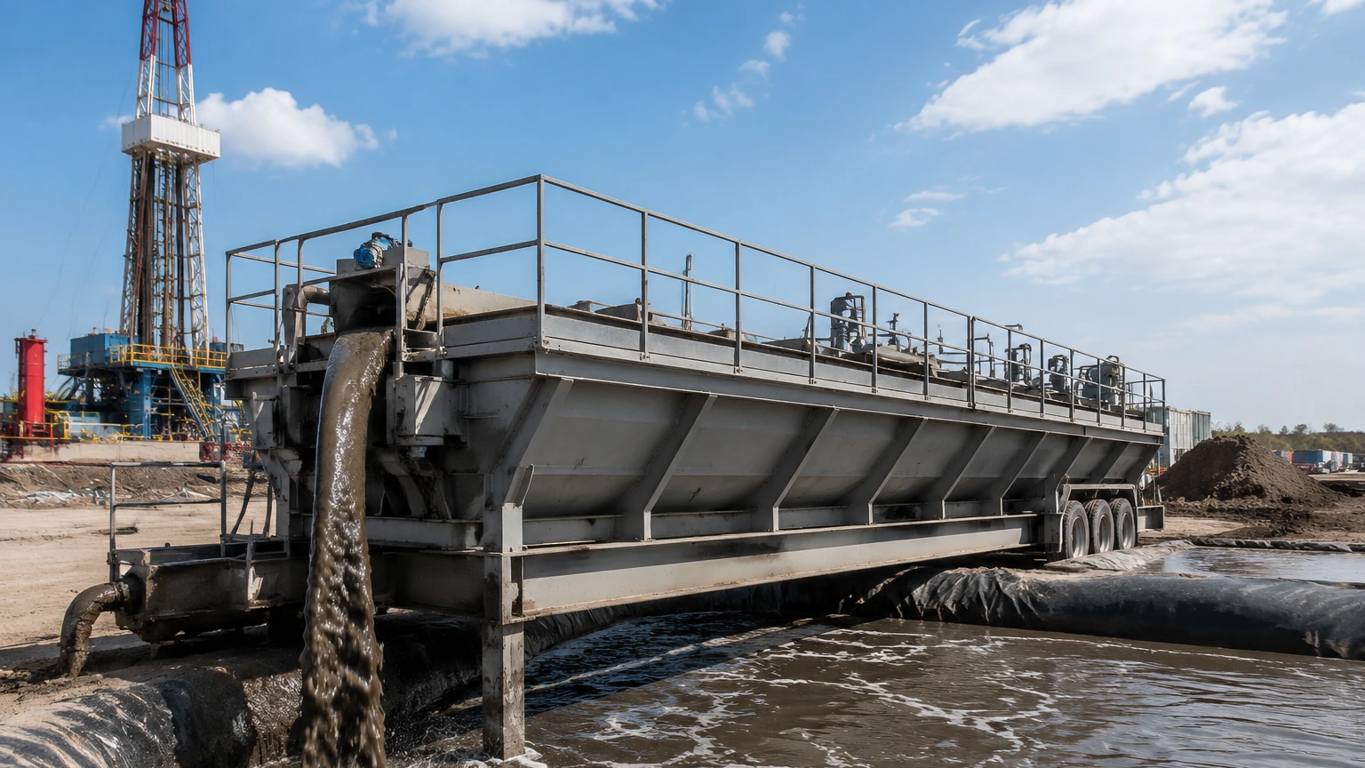
In the oil and gas industry, hydraulic fracturing (fracking) generates significant volumes of wastewater, including flowback and produced water. Managing this fluid on-site is a logistical and environmental challenge. A mobile wastewater clarifier for fracking provides a portable, high-capacity solution for removing suspended solids, oils, and chemical precipitates before the water is reused or disposed of. For engineers and site managers, selecting the right clarification system—and the instrumentation that monitors it—is critical for maintaining operational uptime and regulatory compliance.
Effective clarification relies on the precise separation of solids from liquids. Because mobile units must operate in diverse environments with varying water chemistries, the integration of reliable level measurement technology is essential. This guide explores the technical requirements of mobile clarifiers and the instrumentation strategies necessary for efficient fracking water treatment.
Understanding the Role of Mobile Clarifiers in Hydraulic Fracturing
Fracking wastewater is a complex mixture containing sand, salts, heavy metals, hydrocarbons, and friction reducers. Mobile wastewater clarifiers are designed to be transported via trailer to well pads, where they process large volumes of fluid in a continuous or batch flow.
The primary objective of a mobile wastewater clarifier for fracking is to reduce the Total Suspended Solids (TSS) and Turbidity. The process typically involves several stages:
1. Coagulation and Flocculation: Chemicals are added to the wastewater to neutralize charges and bind small particles into larger "flocs."
2. Sedimentation: The fluid enters the clarification chamber where the velocity is reduced, allowing the heavier flocs to settle to the bottom as sludge.
3. Clarified Effluent Removal: Clean water is drawn from the top of the tank.
4. Sludge Management: Settled solids are thickened and removed for dewatering or disposal.
To automate these stages, operators must monitor tank levels, sludge blanket heights, and chemical feed inventory. For a comprehensive overview of available technologies, engineers often refer to the Main Page of instrumentation providers to match sensor specifications with fluid properties.
Measurement Principles for Clarification Processes
Before selecting hardware for a mobile wastewater clarifier for fracking, it is vital to understand the physical principles governing level and interface measurement in these systems.
Hydrostatic Pressure
Hydrostatic level transmitters measure the pressure exerted by the liquid column. The relationship is defined by $P = \rho \cdot g \cdot h$, where $P$ is pressure, $\rho$ is liquid density, $g$ is gravity, and $h$ is the height of the liquid. While cost-effective, this method assumes a constant density. In fracking, the density of produced water can fluctuate significantly due to varying salt concentrations (brine), which may introduce errors if not compensated.
Ultrasonic (Time-of-Flight)
Ultrasonic sensors emit high-frequency sound pulses that reflect off the liquid surface. The sensor calculates distance based on the time it takes for the echo to return. This is a non-contact method, making it ideal for corrosive fracking fluids. However, it can be sensitive to foam, heavy vapors, and air temperature fluctuations within the tank.
Radar (Frequency Modulated Continuous Wave)
Modern 80GHz radar transmitters emit a continuous microwave signal. The frequency difference between the emitted and received signal is proportional to the distance. Radar is highly effective for fracking applications because it is unaffected by density changes, steam, or dust. It provides high precision even in the turbulent conditions common during the initial fill stages of a clarifier.
Interface Measurement
In a clarifier, the "interface" is the boundary between the clarified water and the settling sludge blanket. Measuring this interface allows the system to trigger sludge pumping only when necessary. Technologies like Guided Wave Radar (GWR) or specialized ultrasonic sludge blanket detectors are used to track this transition zone.
Key Instrumentation for Monitoring Mobile Wastewater Clarifiers
Mobile units require robust sensors that can withstand transport vibrations and rapid setup. Welk provides a range of industrial instruments tailored for these demanding environments.
* Radar Level Meters: Used for primary tank level monitoring. Non-contact radar is preferred for mobile units because it requires minimal maintenance and is not fouled by the oils or chemicals present in flowback water.
* Ultrasonic Level Sensors: Often utilized for chemical storage tanks (coagulants and polymers) where the medium is relatively stable and clean.
* Sludge Blanket Level Switches: Point level switches, such as tuning fork or capacitive types, can be installed at specific heights in the clarifier cone to prevent sludge overfill.
* Hydrostatic Transmitters: Frequently used in the final effluent tanks where the water density is more predictable and the cost-per-unit is a primary consideration.
Selection Table for Level Measurement in Fracking Water Treatment
Choosing the right technology depends on the specific stage of the clarification process. The following table provides a general guideline for instrument selection in a mobile wastewater clarifier for fracking.
| Application | Recommended Technology | Advantages | Limitations |
| :— | :— | :— | :— |
| Main Clarifier Tank | 80GHz Non-contact Radar | High accuracy; unaffected by foam/vapor. | Higher initial cost than ultrasonic. |
| Sludge Blanket Detection | Guided Wave Radar (GWR) | Precise interface tracking. | Probe may require periodic cleaning. |
| Chemical Feed Totes | Ultrasonic Level Sensor | Low cost; easy to install on small tanks. | Sensitive to heavy chemical vapors. |
| Effluent Monitoring | Hydrostatic Transmitter | Robust; simple integration. | Requires constant fluid density. |
| High-Level Alarm | Tuning Fork Switch | Fail-safe; ignores foam/coating. | Point level only; no continuous data. |
Installation and Maintenance Considerations for Mobile Units
When integrating level sensors into a mobile wastewater clarifier for fracking, engineers must account for the unique physical constraints of portable equipment.
Mounting and Orientation
Sensors should be mounted away from inlet pipes and agitators to avoid signal interference. For radar and ultrasonic units, the beam must have a clear path to the liquid surface. If the clarifier uses internal baffles to slow flow, the sensor should be positioned in a zone that represents the average tank level.
Vibration and Mechanical Stress
Mobile clarifiers are subject to significant mechanical stress during transit. All instrumentation should be securely fastened with vibration-resistant mounts. NEMA 4X or IP67-rated enclosures are mandatory to protect electronics from the harsh outdoor environments of oil fields.
Calibration for Varying Fluids
Since a mobile wastewater clarifier for fracking may move between different well sites, the fluid properties (such as dielectric constant or density) may change. Radar sensors are generally "set and forget" because they rely on the dielectric constant of the surface, which is usually sufficient in water-based fluids. However, hydrostatic sensors may require recalibration if the salinity of the produced water changes significantly.
Limitations and Operational Challenges
While mobile clarifiers are highly effective, they face specific technical limitations:
* Solids Buildup: High concentrations of sand and silt can lead to "bridging" in the clarifier cone. Level sensors must be positioned to monitor the sludge level accurately to prevent the pump from running dry or the tank from overflowing.
* Chemical Interference: The polymers used in flocculation can be extremely sticky. If using contact-based sensors like GWR or hydrostatic probes, regular cleaning schedules must be established to prevent "ghost" readings caused by material buildup.
* Foaming: Fracking fluids often contain surfactants that create thick foam. This can absorb ultrasonic signals, leading to a loss of echo. In these cases, 80GHz radar is the superior choice as it penetrates foam more effectively.
Frequently Asked Questions (FAQ)
Q: Why is radar preferred over ultrasonic for fracking clarifiers?
A: Fracking sites often involve temperature swings and chemical vapors. Radar uses electromagnetic waves which are unaffected by air density or vapor, whereas ultrasonic sound waves can be deflected or slowed by these factors, leading to inaccuracies.
Q: How do I measure the sludge level in a mobile unit?
A: The most reliable method is using an interface level transmitter or a series of point level switches. These detect the difference in density or conductivity between the clarified water and the thickened sludge.
Q: Can these sensors handle the high salinity of produced water?
A: Yes, but material selection is key. Sensors with PVDF or PTFE-coated wetted parts should be used to prevent corrosion from high chloride concentrations.
Q: What is the maintenance cycle for level sensors in this application?
A: For non-contact sensors, maintenance is minimal—usually a visual inspection every few months. Contact sensors may require monthly cleaning depending on the stickiness of the sludge and the effectiveness of the flocculants.
Conclusion
A mobile wastewater clarifier for fracking is a vital component of modern oilfield water management. By effectively removing solids and contaminants, these units enable water recycling and reduce the environmental footprint of drilling operations. However, the efficiency of the clarifier is only as good as the data driving its automation. Selecting high-quality radar, ultrasonic, and hydrostatic instruments ensures that the clarification process remains stable, even as fluid conditions change from one well site to the next. For detailed product specifications and engineering support, visiting the Main Page of a dedicated manufacturer like Welk is the recommended first step in system design.