Multivariable Transmitters
Multivariable Transmitters
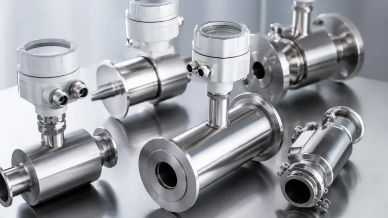
In the landscape of industrial process control, the demand for higher accuracy and reduced complexity has led to the widespread adoption of multivariable transmitters. Traditionally, measuring a complex process variable—such as the mass flow of steam or the precise level of a liquid in a pressurized vessel—required multiple independent sensors for differential pressure, static pressure, and temperature. A multivariable transmitter integrates these measurements into a single device, performing real-time compensation calculations to provide more accurate and reliable data. This guide explores the engineering principles, selection criteria, and practical application of these instruments in modern industrial environments.
Measurement Principles of Multivariable Transmitters
To understand why multivariable transmitters are essential, one must first look at the physics of fluid measurement. Most process variables are influenced by changes in temperature and pressure. For instance, the density of a gas or steam fluctuates significantly with temperature changes, which directly affects flow and level calculations.
The Core Sensors
A standard multivariable transmitter typically incorporates three primary sensing elements:
1. Differential Pressure (DP) Sensor: Measures the difference in pressure between two points. In level applications, this is the pressure difference between the bottom and the top of a tank.
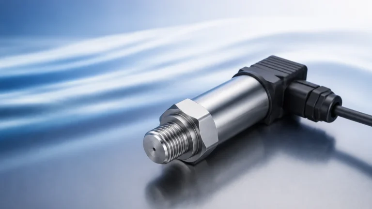
2. Static Pressure (SP) Sensor: Measures the absolute or gauge pressure within the system. This is critical for calculating fluid density and characterizing the physical state of the medium.
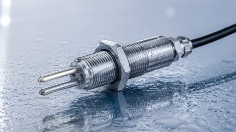
3. Process Temperature (PT) Sensor: Usually an external RTD (Resistance Temperature Detector) or thermocouple input, this measures the heat of the process fluid.
The Compensation Logic
The transmitter’s internal microprocessor uses these three inputs to solve complex equations in real-time. For example, in hydrostatic level measurement, the formula for level is $L = \Delta P / (\rho \cdot g)$, where $\Delta P$ is differential pressure, $\rho$ is density, and $g$ is gravity. Since density $(\rho)$ is a function of both pressure and temperature, a multivariable transmitter can update the density value continuously, providing a compensated level reading that remains accurate even as process conditions shift.
Comparison: Multivariable vs. Single Variable Transmitters
Choosing between a multivariable approach and a traditional multi-sensor array involves weighing installation costs against long-term accuracy requirements. The following table provides a technical comparison for engineering reference.
| Feature | Single Variable (DP Only) | Multivariable Transmitter |
| :— | :— | :— |
| Measured Variables | 1 (Differential Pressure) | 3+ (DP, Static Pressure, Temp) |
| Calculated Outputs | Volumetric Flow / Raw Level | Mass Flow / Compensated Level |
| Installation Points | 3 (DP, P, and T Taps) | 1 (Integrated Manifold) |
| Process Penetrations | Multiple | Minimized |
| Wiring Complexity | High (Multiple cable runs) | Low (Single cable run) |
| Accuracy | Varies with process stability | High (Compensated for density) |
| Maintenance | Multiple devices to calibrate | Single device calibration |
Applications in Level and Flow Measurement
While often associated with flow, multivariable transmitters are indispensable in specific level measurement scenarios where fluid properties are volatile.
Pressurized Vessel Level Measurement
In closed tanks containing liquefied gases or high-pressure steam, the vapor space above the liquid exerts significant pressure. A standard DP transmitter may struggle if the temperature fluctuates, as the density of both the liquid and the vapor will change. A multivariable transmitter accounts for these changes, ensuring that the level reading reflects the actual mass or volume of the product rather than a value skewed by thermal expansion.
Saturated and Superheated Steam
Steam measurement is perhaps the most common application for these devices. Because steam is highly compressible, measuring only the differential pressure across an orifice plate is insufficient. By integrating static pressure and temperature, the multivariable transmitter can calculate the mass flow of steam (kg/h or lb/h) with high precision, which is vital for energy billing and boiler efficiency monitoring.
For engineers looking to integrate these solutions into broader automation systems, it is helpful to Review product options and application support to ensure compatibility with existing tank geometries and communication protocols.
Key Evaluation Criteria for Selection
When specifying a multivariable transmitter for an industrial project, several technical factors must be confirmed to ensure long-term reliability.
1. Accuracy and Rangeability
Rangeability, or turndown ratio, refers to the ratio between the maximum and minimum measurable flow or pressure. High-quality multivariable transmitters offer turndown ratios of 10:1 or higher without significant loss of accuracy. Ensure the device’s accuracy specification (typically expressed as a percentage of the calibrated span) meets the requirements of the specific process loop.
2. Communication Protocols
Most modern units support digital communication protocols. The choice depends on the existing control system (PLC/DCS):
* HART (Highway Addressable Remote Transducer): The most common protocol, allowing digital data to be superimposed on a standard 4-20mA analog signal.
* Modbus RS-485: Preferred for remote locations or integration into SCADA systems where multiple devices are daisy-chained.
* Foundation Fieldbus / Profibus PA: Used in complex plant architectures for high-speed digital integration.
3. Material Compatibility
The wetted parts of the transmitter—the diaphragms and process flanges—must be compatible with the process fluid. Standard materials include 316L Stainless Steel, but corrosive applications may require Hastelloy C-276, Monel, or Tantalum coatings.
4. Environmental and Safety Ratings
For hazardous areas (oil and gas, chemical processing), the transmitter must carry appropriate certifications such as ATEX, IECEx, or UL/CSA for intrinsic safety or explosion-proof housing. Additionally, check the Ingress Protection (IP) rating; IP66 or IP67 is standard for outdoor industrial use.

Installation Considerations and Best Practices
Correct installation is critical for the performance of multivariable transmitters. Because these devices often rely on impulse lines to reach the process fluid, the following guidelines should be followed:
* Impulse Piping: Keep impulse lines as short as possible to minimize lag and potential for clogging. For gas applications, the transmitter should be mounted above the process pipe to allow condensate to drain back. For liquid and steam, it should be mounted below to prevent gas bubbles from entering the sensor.
* Manifold Valves: Always use a 3-way or 5-way valve manifold. This allows the transmitter to be isolated, vented, and zero-checked without shutting down the entire process line.
* Temperature Sensor Placement: The RTD or thermocouple should be installed downstream of the primary flow element (like an orifice plate) at a distance specified by ISO 5167 or AGA standards to avoid flow disturbance.
* Thermal Insulation: In high-temperature applications, ensure the transmitter electronics are protected from radiant heat. Conversely, in cold climates, impulse lines may require heat tracing to prevent freezing.
Limitations and Common Risks
Despite their versatility, multivariable transmitters are not a universal solution for every application. Engineers should be aware of the following limitations:
* Single Point of Failure: Because the device integrates three sensors, a failure in the electronics or the primary DP cell will result in the loss of all three process variables. In safety-critical loops (SIL rated), redundant single-variable transmitters may be preferred.
* Complexity of Configuration: Setting up a multivariable transmitter requires more data than a simple DP cell. The user must input fluid properties (density, viscosity, isentropic exponent) into the transmitter's flow computer. Incorrect data entry will lead to systematic measurement errors.
* Initial Cost: The upfront cost of a multivariable unit is higher than a single-variable transmitter. However, this is usually offset by reduced wiring, fewer pipe penetrations, and lower installation labor costs.
Frequently Asked Questions (FAQs)
Q: Can a multivariable transmitter measure the level of solids?
A: Generally, no. Multivariable transmitters are designed for fluids (liquids, gases, and steam) where hydrostatic pressure and density compensation are applicable. For solids, technologies like radar or ultrasonic sensors are more appropriate.
Q: How often should these devices be calibrated?
A: Calibration frequency depends on the criticality of the process and the stability of the environment. Most manufacturers recommend a bench check every 1 to 2 years. However, many modern units feature advanced diagnostics that monitor sensor health and can alert operators to drift.
Q: Is an external temperature sensor always required?
A: For the highest accuracy in mass flow or compensated level, an external RTD is required because the transmitter's internal temperature sensor only measures the temperature of the electronics or the sensor body, not the process fluid itself.
Q: What is the typical operating temperature range?
A: Standard electronics can operate between -40°C and 85°C (-40°F to 185°F). For the process fluid, the limit is determined by the fill fluid in the remote seals or impulse lines, which can handle temperatures exceeding 400°C (752°F) with proper capillary systems.
Conclusion and Next Steps
Multivariable transmitters represent a significant advancement in process instrumentation, offering a streamlined approach to complex measurements. By integrating multiple sensing elements and on-board computational power, they provide a level of data integrity that single-variable devices cannot match, particularly in fluctuating temperature and pressure environments.
Before proceeding with an upgrade or a new installation, project managers should confirm the chemical compatibility of wetted parts, the required communication protocol for the existing DCS, and the specific fluid dynamics of the application. For detailed technical specifications and to explore how these instruments fit into a comprehensive level measurement strategy, engineers are encouraged to consult professional manufacturer resources and Review product options and application support to ensure the selected solution aligns with operational goals and safety standards.