Natural Gas Flow Sensor
Natural Gas Flow Sensor
In the landscape of industrial automation and process control, the natural gas flow sensor stands as a critical component for ensuring efficiency, safety, and fiscal accountability. Whether used for custody transfer, burner control, or monitoring leakages in complex piping networks, selecting the correct sensor technology requires a deep understanding of fluid dynamics and gas properties. Natural gas, primarily composed of methane but often containing heavier hydrocarbons, CO2, and nitrogen, presents unique challenges due to its compressibility and varying density under different pressure and temperature conditions.
This guide provides a comprehensive technical overview of natural gas flow sensor technologies, their operating principles, and the engineering considerations necessary for successful deployment in industrial environments. For professionals seeking a broader range of instrumentation solutions, including advanced level measurement systems, visiting the Main Page of our technical catalog provides further insights into integrated process monitoring.
Measurement Principles of Natural Gas Flow Sensors
Measuring the flow of natural gas is significantly more complex than measuring liquids because gases are highly compressible. To provide accurate data, sensors must either measure mass flow directly or compensate for pressure and temperature to calculate the "standard" volume (e.g., Normal cubic meters per hour, Nm³/h). Below are the primary measurement principles utilized in modern natural gas flow sensors.
Thermal Dispersion (Mass Flow)
Thermal mass flow sensors operate on the principle of thermal dispersion. The sensor typically consists of two RTD (Resistance Temperature Detector) probes: one that measures the ambient gas temperature and another that is heated to a specific temperature above the ambient. As natural gas flows past the heated sensor, it carries heat away. The amount of energy required to maintain the temperature differential is directly proportional to the mass flow rate of the gas.
Because this technology measures the number of molecules passing the sensor, it does not require additional pressure or temperature compensation to provide mass flow data. This makes it an excellent natural gas flow sensor for applications involving low-pressure lines and fluctuating temperatures.
Vortex Shedding
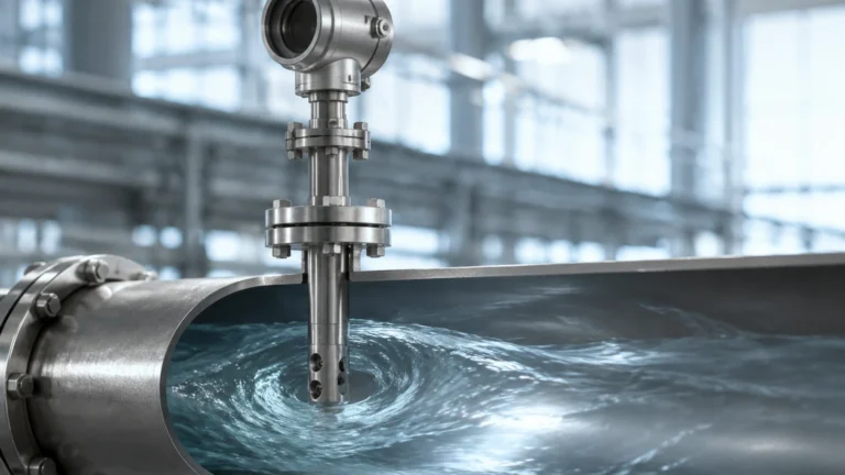
Vortex flow meters utilize the Karman Vortex Street principle. A "bluff body" is placed in the path of the gas flow. As the gas hits this body, it creates alternating vortices on either side. The frequency of these vortices is directly proportional to the velocity of the gas. By multiplying the velocity by the cross-sectional area of the pipe, the volumetric flow rate is determined.
Vortex sensors are highly durable as they have no moving parts. However, they require a minimum Reynolds number to function accurately, meaning they may not be suitable for very low-flow applications.
Turbine Measurement
Turbine flow meters consist of a multi-bladed rotor mounted on bearings within the pipe. The moving gas causes the rotor to spin at a speed proportional to the gas velocity. A magnetic pickup or optical sensor detects the rotation of the blades. Turbine meters are highly accurate and are frequently used in custody transfer applications where precise billing is required. However, they are mechanical devices and are susceptible to wear and damage from debris or "slugs" of liquid in the gas stream.
Ultrasonic (Transit-Time)
Ultrasonic natural gas flow sensors use sound waves to measure velocity. Transducers are mounted on opposite sides of the pipe. One sends a signal downstream, and the other sends a signal upstream. The difference in the time it takes for the signals to reach their destination (the transit time) is used to calculate the gas velocity. This technology is non-intrusive, offers a high turndown ratio, and handles high-pressure applications exceptionally well.
Differential Pressure (DP)
DP flow meters, such as orifice plates or Venturi tubes, create a constriction in the flow path. According to Bernoulli’s principle, this constriction causes an increase in velocity and a corresponding drop in pressure. The square root of the pressure drop is proportional to the flow rate. While traditional, these systems require secondary transmitters for pressure and temperature to calculate mass flow accurately.
Key Evaluation Criteria for Selection
Choosing the right natural gas flow sensor involves balancing technical requirements with budget constraints. Engineers must evaluate the following parameters before procurement:
1. Accuracy and Repeatability
For internal process monitoring, an accuracy of ±2% to ±5% might suffice. However, for custody transfer (where gas is bought or sold), accuracy must often be better than ±0.5%. Repeatability is equally important, ensuring the sensor provides the same reading under identical conditions over time.
2. Turndown Ratio
The turndown ratio defines the range over which the sensor can measure accurately. For example, a 100:1 turndown ratio means a sensor calibrated for 1000 m³/h can accurately measure down to 10 m³/h. Thermal mass sensors typically offer the highest turndown ratios, while DP meters are more limited (often 4:1 or 5:1).
3. Operating Pressure and Temperature
Natural gas is often transported at high pressures (up to 100 bar or more). The sensor housing and internal components must be rated for these pressures. Furthermore, temperature fluctuations affect gas density; therefore, sensors that do not measure mass directly must have integrated or external compensation.
4. Gas Composition
Natural gas is rarely pure methane. The presence of ethane, propane, nitrogen, or hydrogen sulfide (H2S) can affect the thermal properties and density of the gas. It is vital to confirm that the natural gas flow sensor is calibrated for the specific gas mix of the application.
Selection Table: Technology Comparison
| Technology | Typical Accuracy | Turndown Ratio | Pressure Drop | Moving Parts | Best Use Case |
| :— | :— | :— | :— | :— | :— |
| Thermal Mass | ±1% of Reading | 100:1 | Negligible | No | Low pressure, sub-metering |
| Vortex | ±1% of Rate | 20:1 | Moderate | No | High-velocity process gas |
| Turbine | ±0.5% to ±1% | 15:1 | High | Yes | Custody transfer, billing |
| Ultrasonic | ±0.5% | 50:1 | None | No | Large diameter, high pressure |
| Orifice (DP) | ±2% to ±3% | 4:1 | High | No | Standard industrial steam/gas |
Installation Considerations and Best Practices
Even the most advanced natural gas flow sensor will fail to provide accurate data if installed incorrectly. Proper installation is the foundation of reliable measurement.
Straight Pipe Requirements
Most flow sensors require a "fully developed flow profile" to operate accurately. Turbulence caused by elbows, valves, or reducers can lead to significant errors. Generally, a minimum of 10 to 20 diameters (10D – 20D) of straight pipe upstream and 5 diameters (5D) downstream is required. If space is limited, flow conditioners (vane-type or perforated plates) may be necessary to straighten the flow.
Orientation and Positioning
For gas applications, sensors should ideally be installed on a horizontal run of pipe. If the gas is "wet" (contains moisture or condensates), the sensor should be positioned at the top of the pipe to prevent liquid from accumulating on the sensing elements. Conversely, for liquid level measurement applications handled by Welk instruments, the focus is often on the vertical orientation of the vessel, but in flow, the horizontal plane is usually preferred.
Hazardous Area Certifications
Natural gas is highly flammable. Any natural gas flow sensor installed in the vicinity of a gas line must meet strict safety standards, such as ATEX (Europe) or IECEx (International). This ensures the device is intrinsically safe or explosion-proof, preventing it from becoming an ignition source in the event of a leak.
Limitations and Common Risks
While modern sensors are robust, several factors can compromise their performance:
* Contamination: Dust, pipe scale, or compressor oil can coat the sensors in thermal mass or ultrasonic meters, leading to drift. Regular inspection and cleaning are necessary in "dirty" gas applications.
* Moisture Content: Water vapor in the gas stream can significantly affect thermal mass sensors, as water has a much higher heat capacity than gas. If moisture is present, a separator should be installed upstream.
* Pressure Drops: Technologies like orifice plates and turbine meters cause a permanent pressure drop in the line. In low-pressure systems, this loss can impact the efficiency of downstream equipment like burners or turbines.
* Vibration: In vortex meters, excessive pipe vibration can be misinterpreted by the sensor as flow, leading to false readings.
The Relationship Between Flow and Level Measurement
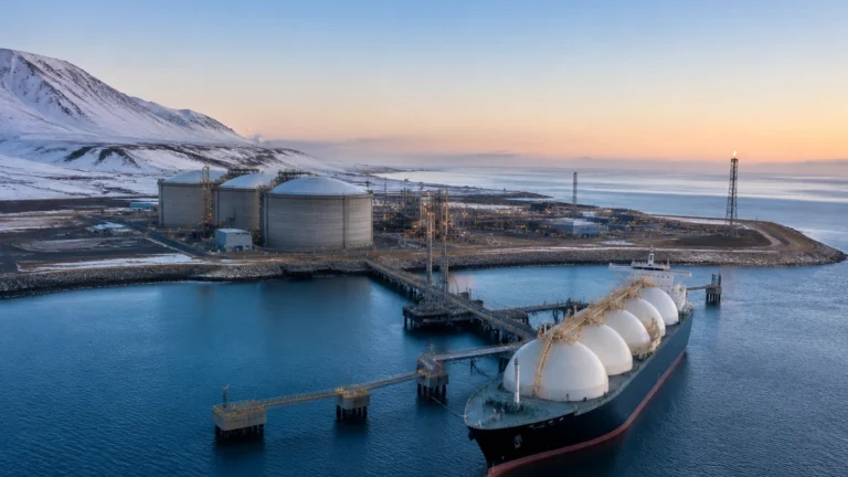
In many industrial setups, flow and level measurement work in tandem. For instance, in a natural gas storage facility, hydrostatic or radar level transmitters (such as those offered by Welk) monitor the volume of liquid natural gas (LNG) or the pressure in storage spheres. Simultaneously, a natural gas flow sensor monitors the rate of withdrawal or injection. Comparing the change in tank level against the integrated flow rate serves as a critical "mass balance" check, helping operators detect leaks or discrepancies in the system.
For engineers designing these integrated systems, exploring the Main Page of specialized manufacturers helps in selecting compatible instruments that can communicate via standard protocols like 4-20mA HART, Modbus, or Foundation Fieldbus.
Frequently Asked Questions (FAQ)
Q: Can a natural gas flow sensor measure other gases?
A: Most sensors can, but they must be recalibrated. Thermal mass sensors, in particular, are highly sensitive to the specific heat capacity of the gas. Using a sensor calibrated for air on natural gas will result in significant errors.
Q: What is the difference between Actual and Standard flow?
A: Actual flow (ACFM) is the volume of gas at the current operating pressure and temperature. Standard flow (SCFM or Nm³/h) is the volume corrected to a standard reference pressure (usually 1.013 bar) and temperature (usually 0°C or 15°C). Most industrial billing and processes use standard flow.
Q: How often should a natural gas flow sensor be calibrated?
A: This depends on the application. For custody transfer, annual calibration is often mandated by law. For general process control, a check every 2 to 3 years is common, provided there is no evidence of drift or contamination.
Q: Are there non-invasive options for gas flow measurement?
A: Yes, clamp-on ultrasonic flow meters can measure gas flow through the pipe wall. However, gas is a poor conductor of sound compared to liquids, so these sensors require high-power transducers and are typically only effective on high-pressure metal pipes.
Conclusion
The selection of a natural gas flow sensor is a technical decision that impacts the safety and profitability of industrial operations. By understanding the physics behind thermal dispersion, vortex shedding, and ultrasonic transit-time, engineers can select a technology that matches their specific pressure, temperature, and accuracy requirements. Proper installation, adherence to straight-run requirements, and regular maintenance ensure that these instruments provide reliable data for years to come. For more information on how to integrate flow data with tank monitoring and industrial level measurement, we invite you to review the resources available on our Main Page.