Non Contact Flow Switch
Non Contact Flow Switch
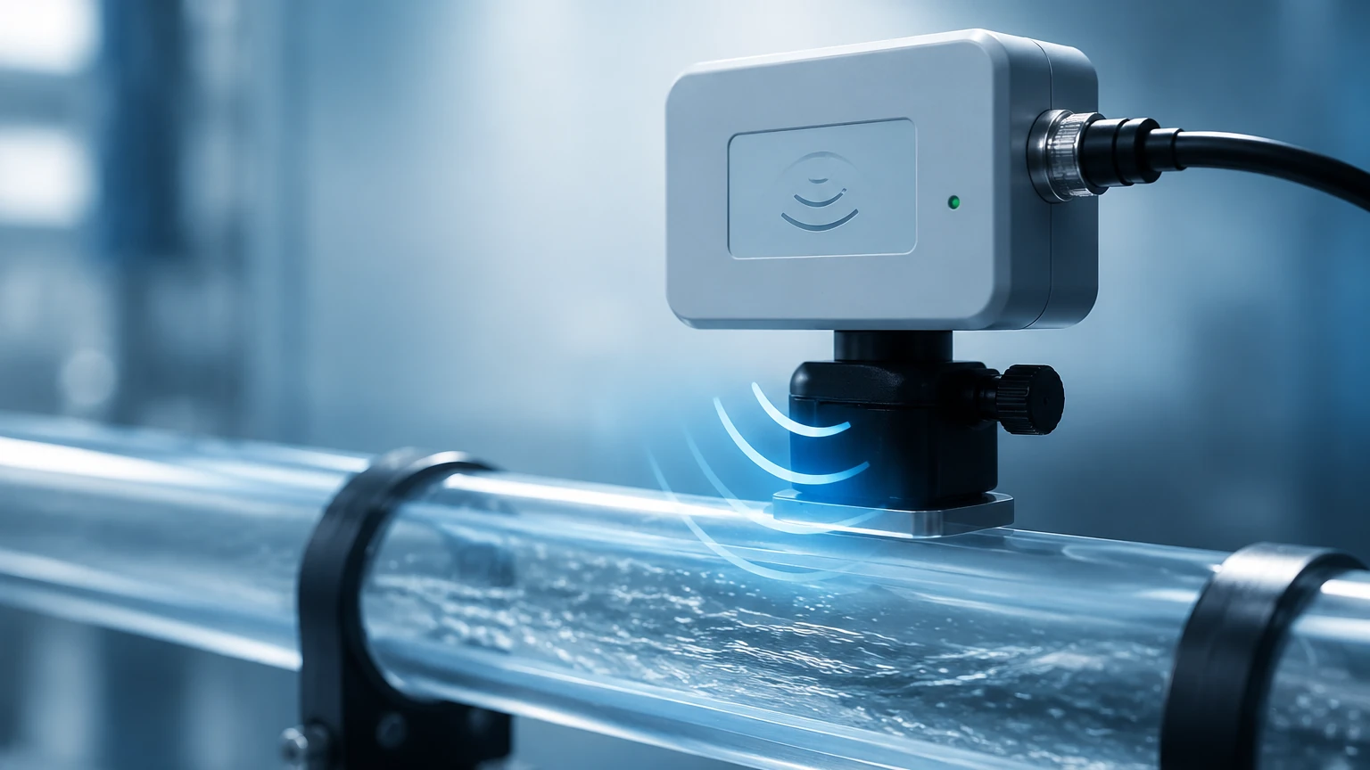
In modern industrial process control, the ability to monitor fluid movement without compromising the integrity of the piping system is a significant engineering advantage. A non contact flow switch is a specialized instrument designed to detect the presence, absence, or rate of flow within a closed conduit without making physical contact with the process media. By utilizing external sensors—typically clamped onto the outside of a pipe—these devices eliminate the risks associated with leak paths, pressure drops, and material incompatibility.
For engineers and plant managers, selecting a non contact flow switch involves understanding the underlying physics of non-invasive sensing. This guide explores the measurement principles, selection criteria, and practical installation requirements for these essential industrial components.
Measurement Principles of Non-Contact Flow Detection
Unlike traditional paddle-wheel or turbine switches that require a mechanical penetration into the pipe, non-contact switches rely on wave propagation and thermal energy. The most common technologies include ultrasonic, microwave, and external thermal dispersion.
Ultrasonic Doppler Effect
The Doppler principle is one of the most widely used methods for non-contact flow switching, particularly in fluids containing suspended solids or aerated bubbles. The switch utilizes a transducer that emits an ultrasonic signal into the pipe. If the fluid is moving, the frequency of the reflected signal (from particles or bubbles) shifts in proportion to the flow velocity. When this frequency shift crosses a pre-defined threshold, the switch changes state (e.g., from NO to NC).
Ultrasonic Transit Time
For clean liquids, transit-time technology is preferred. This method uses a pair of transducers that send and receive ultrasonic pulses through the fluid. The pulse traveling with the flow moves faster than the pulse traveling against it. The switch calculates the time difference to determine flow velocity. While often used for high-precision metering, transit-time switches are highly effective for low-flow detection in high-purity water or chemical applications.
Microwave and Radar Sensing
Microwave flow switches are typically used for solids or liquids in non-metallic pipes (such as PVC, PE, or glass). The sensor emits a low-power microwave beam. Movement within the pipe causes a reflected signal variation known as the "modulation frequency." This technology is exceptionally robust for detecting the flow of powders, granules, or aggressive chemicals in plastic conduits where ultrasonic signals might suffer from attenuation.
External Thermal Dispersion
Though less common for large-diameter pipes, external thermal switches use a heating element and a temperature sensor clamped to the outside of a small-diameter tube. As fluid flows, it carries heat away from the pipe wall. The rate of cooling is proportional to the flow. This method is highly sensitive for micro-flow detection in laboratory or pharmaceutical environments.
Key Advantages in Industrial Applications
Integrating a non contact flow switch into a process provides several strategic benefits over wetted-part alternatives:
1. Zero Pressure Drop: Since no mechanical obstacles are placed in the flow path, the system maintains its hydraulic efficiency.
2. Hygiene and Purity: In food, beverage, and pharmaceutical industries, avoiding contact with the media prevents contamination and eliminates the need for complex CIP (Clean-In-Place) validation for the sensor itself.
3. Corrosion Resistance: Because the sensor is isolated from the fluid, even the most aggressive acids or bases can be monitored using standard sensor housings, provided the pipe material allows signal penetration.
4. Ease of Retrofitting: These switches can be installed on existing piping systems without shutting down the process or cutting into the lines.
For organizations looking to upgrade their monitoring systems, you can Review product options and application support to find solutions tailored to specific industrial environments.
Selection Criteria and Technical Specifications
Choosing the right switch requires a detailed analysis of both the fluid properties and the pipe characteristics. The following table provides a comparison of the primary non-contact technologies.
Technology Selection Table
| Feature | Ultrasonic Doppler | Ultrasonic Transit Time | Microwave/Radar |
| :— | :— | :— | :— |
| Best Fluid Type | Slurries, aerated liquids, wastewater | Clean liquids, oils, deionized water | Powders, granules, liquids in plastic pipes |
| Minimum Solids | >100 ppm (approx. 75 microns) | <1% solids | N/A (Detects any movement) |
| Pipe Material | Metal or plastic | Metal or plastic | Plastic, glass, or ceramic only |
| Sensitivity | Moderate | High | High (for solids) |
| Installation | External Clamp-on | External Clamp-on | External Point-directed |
Pipe and Fluid Considerations
* Pipe Material: Ultrasonic signals travel well through carbon steel, stainless steel, and most plastics. However, pipes with loose liners (like old cement or rubber liners with air gaps) can block the signal.
* Fluid Temperature: While the sensor is external, it must be rated for the surface temperature of the pipe. Standard sensors typically handle up to 120°C (248°F), while specialized high-temperature versions are required for steam or hot oil lines.
* Wall Thickness: Excessively thick pipe walls can attenuate ultrasonic signals. It is essential to confirm the pipe schedule (e.g., Schedule 40 vs. Schedule 80) before final selection.
Installation Guidelines for Reliable Performance
Correct installation is the single most important factor in ensuring the accuracy of a non contact flow switch. Unlike level meters, which often look at a static surface, flow switches must account for turbulence and flow profiles.
1. Straight Pipe Requirements
To ensure a stable flow profile, the switch should be installed on a straight section of pipe. The standard engineering rule is to allow at least 10D (ten times the pipe diameter) of straight pipe upstream and 5D downstream from any elbows, valves, or pumps. For example, on a 50 mm (2 inch) pipe, you should have 500 mm (20 inches) of straight pipe before the sensor.
2. Mounting Orientation
For horizontal pipes, sensors should ideally be mounted at the 3 o'clock or 9 o'clock positions. Mounting on the top (12 o'clock) risks detecting air pockets, while mounting on the bottom (6 o'clock) may lead to interference from settled sediment.
3. Acoustic Coupling
For ultrasonic clamp-on switches, an acoustic coupling agent (grease or gel) must be applied between the transducer face and the pipe wall. This eliminates air gaps that would otherwise reflect the ultrasonic energy. In permanent installations, solid epoxy couplants or specialized stainless-steel straps are used to maintain long-term contact.
Limitations and Common Risks
While non-contact technology is highly versatile, it is not a "universal" solution. Engineers should be aware of the following limitations:
* Pipe Wall Bonding: If a pipe is heavily scaled or has internal buildup, the signal may be absorbed or scattered before it reaches the fluid.
* Signal Interference: High-frequency vibration from nearby pumps or heavy machinery can occasionally introduce noise into ultrasonic sensors. Shielded cabling and proper grounding are mandatory.
* Full Pipe Requirement: Most non-contact switches require the pipe to be completely full to function. If a pipe is only partially full, the signal will reflect off the air-liquid interface, leading to a false "no flow" or "error" signal.
Maintenance and Troubleshooting
One of the primary benefits of the non-contact design is low maintenance. Since there are no moving parts to wear out or orifices to clog, the maintenance cycle is significantly extended. However, periodic checks are still necessary:
* Couplant Inspection: In high-vibration or extreme temperature environments, the coupling gel may dry out over several years. Periodically checking signal strength via the switch's diagnostic interface can identify when re-greasing is required.
* Mounting Tension: Ensure that the stainless-steel clamps or straps have not loosened due to thermal expansion and contraction of the pipe.
* Signal Strength Calibration: If the process fluid changes (e.g., a change in chemical concentration or solids content), the switch sensitivity may need adjustment to prevent false tripping.
Frequently Asked Questions (FAQ)
Q: Can a non contact flow switch work on copper or lined pipes?
A: Yes, they work on copper. For lined pipes, the success depends on the bond between the liner and the pipe wall. If the liner is fused (like Teflon-lined steel), it usually works. If there is an air gap between the liner and the pipe, the signal will not pass through.
Q: What is the minimum flow velocity required for detection?
A: This varies by model, but most ultrasonic switches can detect flow as low as 0.1 m/s (0.3 ft/s). For extremely low flows, transit-time technology is superior to Doppler.
Q: Does pipe vibration affect the switch?
A: Excessive vibration can cause mechanical wear on the mounting straps or introduce electrical noise. Most modern switches include digital filtering to ignore common industrial vibration frequencies, but isolation mounting is recommended in extreme cases.
Q: Is it possible to use these switches on hazardous media?
A: Absolutely. Because the sensor never touches the fluid, it is often the safest choice for toxic, explosive, or highly corrosive media. Ensure the sensor housing itself meets the required area classification (e.g., ATEX or Class I, Div 1).
Conclusion
The non contact flow switch represents a peak of practical engineering, offering a non-invasive, reliable, and low-maintenance solution for flow monitoring. By understanding the specific needs of the fluid and the pipe environment—and by adhering to strict installation standards—industrial operators can significantly improve system uptime and safety. For comprehensive technical data and to explore a full range of industrial measurement instruments, including radar and ultrasonic level sensors, professionals are encouraged to visit the Welk Main Page for further engineering support and product specifications.