Slop Holding Tanks
Slop Holding Tanks
In industrial fluid management and maritime operations, slop holding tanks serve as critical infrastructure for the containment and preliminary treatment of waste liquids. These tanks are designed to collect a mixture of water, oil, chemical residues, and tank cleaning detergents—collectively referred to as "slop." Because the contents of these tanks are often volatile, corrosive, or prone to separation, selecting the correct level measurement technology is essential for operational safety, environmental compliance, and process efficiency.
Effective management of slop holding tanks requires a deep understanding of the physical properties of the stored media. This guide explores the engineering principles behind slop tank monitoring, the selection of appropriate instrumentation, and best practices for installation and maintenance.
The Role of Slop Holding Tanks in Industry
Slop holding tanks are primarily found in oil refineries, petrochemical plants, offshore platforms, and marine vessels. Their main function is to act as a buffer and separation point for contaminated liquids before they are processed by an oil-water separator (OWS) or transported for onshore disposal.
In maritime contexts, slop tanks are governed by strict international regulations, such as MARPOL Annex I, which mandates the monitoring of oil discharge. On land, industrial facilities use these tanks to manage "wash water" from reactor cleaning or runoff from process areas. The liquid inside a slop tank is rarely homogenous; it typically consists of an aqueous phase at the bottom and an organic (oily) phase floating on top, often with a layer of emulsion or foam in between.
Measurement Principles for Slop Tank Monitoring
Accurate level measurement in slop holding tanks is challenging due to the presence of vapors, changing densities, and the potential for coating or buildup on sensors. Engineers must choose between several measurement principles based on the specific tank dynamics.
Radar Level Measurement (Non-Contact)
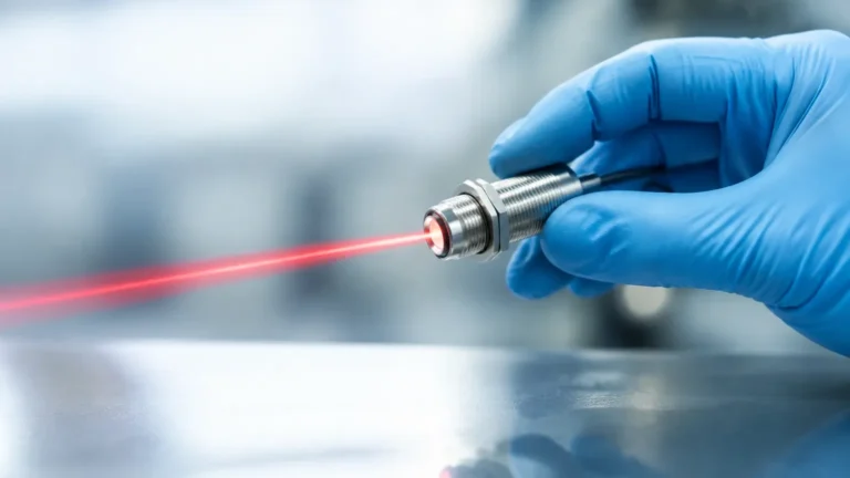
Radar level transmitters utilize the Time-of-Flight (ToF) principle. The sensor emits a high-frequency microwave signal (typically 26 GHz or 80 GHz) toward the liquid surface. The signal reflects off the surface and returns to the sensor. The distance is calculated based on the time it takes for the pulse to travel to the surface and back.
* Advantages: Radar is unaffected by changes in pressure, temperature, or the presence of vapors and dust. High-frequency 80 GHz radar is particularly effective in slop tanks because its narrow beam angle can avoid internal obstructions like heating coils or ladders.
* Limitations: The dielectric constant (εr) of the upper liquid layer must be sufficient to reflect the signal. If the oil layer is very thin or has an extremely low dielectric constant, the signal might pass through to the water interface.
Ultrasonic Level Measurement
Ultrasonic sensors also use the ToF principle but rely on sound waves rather than electromagnetic waves. The sensor sends a pulse that reflects off the liquid surface.
* Advantages: Cost-effective for non-hazardous, water-based slop applications where the environment is relatively stable.
* Limitations: Sound speed is affected by air temperature and gas composition. In slop holding tanks where hydrocarbon vapors are present, ultrasonic accuracy can degrade significantly. Additionally, heavy foam can absorb the sound pulse, leading to signal loss.
Hydrostatic Pressure Measurement
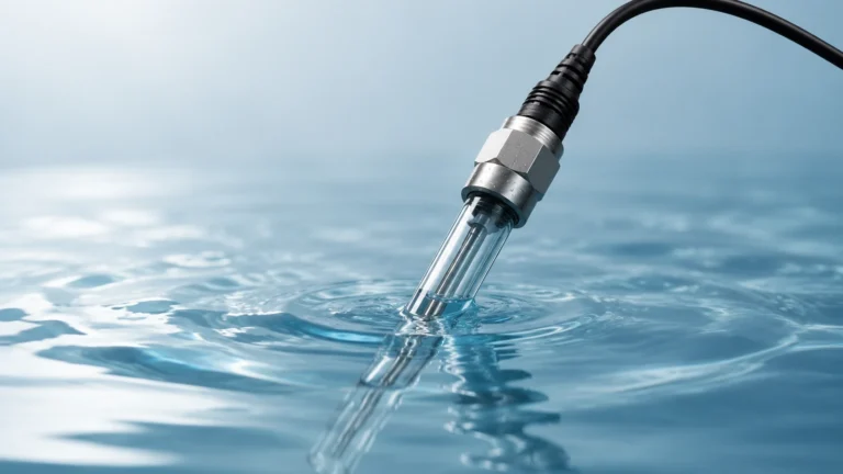
This method measures the pressure exerted by the liquid column at the bottom of the tank. Since pressure is proportional to the height of the liquid and its density ($P = \rho \cdot g \cdot h$), the level can be calculated if the density is known.
* Advantages: Simple to install and highly reliable for liquids with a consistent density.
* Limitations: In slop tanks, the density often changes as oil and water separate. If the ratio of oil to water fluctuates, a standard hydrostatic sensor will provide an inaccurate level reading unless density compensation is used.
Magnetic Level Gauges
Magnetic level gauges are mounted externally to the tank (bypass style). A float containing a magnet moves with the liquid level inside a chamber, flipping magnetized flaps on an external indicator to provide a visual reading.
* Advantages: Provides a clear, local visual indication without requiring power. They are excellent for high-pressure or high-temperature slop applications.
* Limitations: They require mechanical installation into the side of the tank and are susceptible to clogging if the slop contains heavy solids or high-viscosity wax.
Selection Criteria for Slop Tank Instrumentation
When evaluating instrumentation for slop holding tanks, engineers should consider the following factors to ensure long-term reliability:
1. Media Composition: Is the slop primarily water, crude oil, or a mix of aggressive chemicals? Corrosive slop requires sensors made from PTFE, PVDF, or high-grade stainless steel.
2. Foam and Turbulence: If the tank is filled from the top or contains agitators, foam and surface turbulence are likely. Non-contact radar is generally more resilient to these conditions than ultrasonic sensors.
3. Vapor Space: Slop tanks often contain volatile organic compounds (VOCs). Sensors must be rated for hazardous areas (Ex-proof or Intrinsically Safe) and be able to penetrate heavy vapor blankets.
4. Tank Geometry: Small, narrow tanks or tanks with internal heating coils require sensors with narrow beam angles to prevent false echoes.
Technology Comparison Table
| Feature | Radar (80 GHz) | Ultrasonic | Hydrostatic | Magnetic Gauge |
| :— | :— | :— | :— | :— |
| Accuracy | High (±1 mm) | Moderate (±0.25%) | Moderate | Moderate |
| Vapor Resistance | Excellent | Poor | Excellent | Excellent |
| Foam Resistance | Good | Poor | Excellent | Excellent |
| Maintenance | Low (No moving parts) | Low | Medium (Cleaning) | Medium (Cleaning) |
| Cost | Higher | Lower | Moderate | Moderate |
| Installation | Top-mounted | Top-mounted | Bottom/Side | Side-mounted |
For a comprehensive range of industrial measurement tools suitable for these environments, engineers can Review product options and application support on our Main Page.
Installation Considerations for Slop Holding Tanks
Proper installation is as critical as selecting the right technology. Poorly placed sensors often lead to erratic readings and frequent maintenance alarms.
Nozzle Placement
For non-contact sensors (Radar and Ultrasonic), the sensor should be mounted away from the tank wall to avoid interference from weld seams or scaling. Ideally, the sensor should be positioned at 1/4 to 1/6 of the tank diameter from the wall. It must also be kept away from the fill pipe to prevent the incoming liquid stream from interfering with the signal.
Avoiding Internal Obstructions
Many slop holding tanks are equipped with steam heating coils to keep the oil fluid or agitators to prevent solids from settling. When installing a radar sensor, the beam path must be clear of these obstructions. If an obstruction cannot be avoided, "False Echo Suppression" software in modern transmitters can be used to map out and ignore these static reflections.
Stilling Wells and Bypass Chambers
In applications with excessive foam or extreme turbulence, installing the level sensor inside a stilling well (a vertical pipe inside the tank) can provide a calm surface for measurement. This is particularly effective for radar sensors, as the pipe acts as a waveguide, concentrating the signal and eliminating surface ripples.

Limitations and Common Challenges
Despite advances in technology, slop holding tanks present unique challenges that require specific engineering solutions.
* Interface Measurement: Often, the goal is not just to know the total level, but to know where the oil ends and the water begins. Guided Wave Radar (GWR) is frequently used for this purpose. A probe is submerged in the liquid; part of the signal reflects off the upper oil layer, while the remainder continues through the oil to reflect off the water interface.
* Paraffin and Wax Buildup: In colder climates or with heavy crude slop, wax can build up on probes or tank walls. Non-contact radar is preferred here because it does not touch the media. If a contact-based probe is used, it may require periodic cleaning or specialized coatings to prevent "bridging."
* Environmental Regulations: Slop tanks are often part of a safety-critical system. Overfill protection sensors (Level Switches) should be installed as a redundant system independent of the continuous level transmitter to prevent accidental spills.
Frequently Asked Questions (FAQs)
Q: Can I use an ultrasonic sensor in a slop tank containing hydrocarbons?
A: It is generally not recommended. Hydrocarbon vapors change the speed of sound in the tank's headspace, leading to significant measurement errors. Radar is a much more reliable choice for such environments.
Q: How do I handle heavy foam in a slop tank?
A: Heavy foam can be a challenge for both radar and ultrasonic sensors. If foam is a constant issue, a hydrostatic pressure transmitter or a magnetic level gauge is often the most reliable solution, as they are unaffected by surface conditions.
Q: What is the benefit of 80 GHz radar over 26 GHz radar for slop tanks?
A: 80 GHz radar has a much narrower beam (typically 3° to 4°), which allows it to be installed in smaller nozzles and makes it easier to avoid internal tank structures like heating coils or support beams.
Q: Are metric units standard for these instruments?
A: Yes, most industrial level transmitters are configured in metric units (meters or millimeters) by default, though they can be toggled to imperial units (inches or feet) depending on the regional requirements of the project.
Summary of Best Practices
To ensure the effective operation of slop holding tanks, engineers should prioritize non-contact measurement technologies where possible to minimize maintenance. Radar remains the gold standard for accuracy and reliability in the presence of vapors and varying liquid compositions. However, the choice must always be balanced against the specific chemical properties of the slop and the physical constraints of the tank. Regular calibration and the use of redundant high-level switches are essential components of a robust waste management strategy.
For more detailed technical specifications and to explore specific models for your application, visit our Main Page.