Non Invasive Flow Meter
Non Invasive Flow Meter
In modern industrial processing, the ability to measure fluid dynamics without compromising the integrity of the piping system is a significant engineering advantage. A non invasive flow meter, primarily utilizing ultrasonic technology, allows operators to capture precise flow data from the outside of a pipe. This eliminates the need for pipe cutting, welding, or process downtime, making it an essential tool for sectors ranging from water treatment to chemical processing and oil and gas production.
For engineers and facility managers, understanding the underlying physics and selection criteria for these instruments is crucial. While traditional inline meters require direct contact with the media, non-invasive solutions rely on acoustic signals to penetrate pipe walls and interact with the moving fluid. This guide provides a technical overview of how these systems function, their practical applications, and the critical factors to consider during selection and installation.
Measurement Principles: Transit-Time vs. Doppler
Non-invasive flow measurement is almost exclusively achieved through ultrasonic technology. There are two primary methods used to calculate flow velocity: Transit-Time and Doppler Effect. Choosing the correct principle depends entirely on the characteristics of the fluid being measured.
Transit-Time Ultrasonic Flow Meters
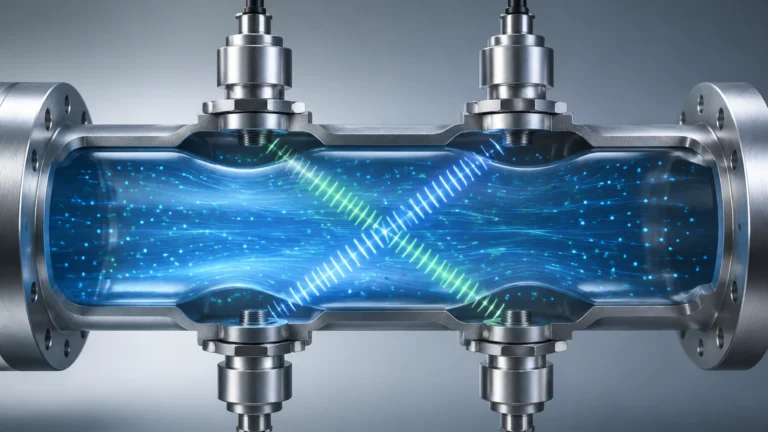
Transit-time meters utilize a pair of transducers, both acting as transmitters and receivers. They are mounted on the outside of the pipe, one upstream and one downstream. The meter sends a pulse of ultrasonic energy from the upstream transducer to the downstream one, and then reverses the process.
When the fluid is moving, the pulse traveling with the flow (downstream) moves faster than the pulse traveling against the flow (upstream). The time difference between these two signals is directly proportional to the flow velocity. This method is highly accurate for clean liquids, such as treated water, oils, and chemicals, where the concentration of suspended solids or entrained air is less than 2% by volume.
Doppler Effect Flow Meters
The Doppler method relies on the frequency shift of a reflected ultrasonic signal. A transducer transmits a continuous high-frequency sound into the pipe. This sound reflects off "discontinuities" within the fluid—such as suspended solids, grit, or air bubbles. Because these particles are moving at the same velocity as the fluid, the reflected signal returns to the receiver at a shifted frequency.
This frequency shift (the Doppler Effect) is used to calculate the flow rate. Unlike transit-time meters, Doppler meters require a minimum concentration of particles or bubbles (typically at least 100 parts per million and a size of 75 microns or larger) to function correctly. They are the preferred choice for slurries, wastewater, and aerated liquids.
Key Components of a Non Invasive Flow Meter System
A complete non-invasive measurement setup consists of three primary components:
1. Transducers (Sensors): These are clamped to the exterior of the pipe. They convert electrical energy into ultrasonic pulses and vice versa. High-quality transducers are designed to withstand industrial environments, including extreme temperatures and corrosive atmospheres.
2. Signal Processor (Transmitter): This unit houses the electronics that generate the ultrasonic signals and process the returned data. It calculates the flow rate based on the programmed pipe parameters and provides outputs such as 4-20mA, Modbus, or pulse signals for integration into a SCADA or PLC system.
3. Mounting Hardware: This includes the rails, chains, or clamps that secure the transducers to the pipe. It also involves the use of an acoustic coupling agent (grease or gel) to ensure there is no air gap between the transducer face and the pipe surface, which would otherwise block the ultrasonic signal.
Selection Criteria and Technical Specifications
Selecting a non invasive flow meter requires a detailed understanding of the application environment. Unlike level measurement instruments—such as those found on the Main Page of industrial catalogs—flow meters are sensitive to the internal geometry and material properties of the conduit.
Fluid Properties
* Cleanliness: As established, clean fluids require transit-time technology, while "dirty" fluids require Doppler.
* Viscosity: High-viscosity fluids can affect the flow profile (laminar vs. turbulent), which the signal processor must account for to maintain accuracy.
* Temperature: Standard transducers typically handle up to 80°C (176°F), but high-temperature variants are available for applications reaching 250°C (482°F) or higher.
Pipe Characteristics
* Material: Ultrasonic signals travel well through most metals (carbon steel, stainless steel, ductile iron) and plastics (PVC, HDPE). However, materials like concrete-lined pipes or heavily corroded pipes can attenuate the signal significantly.
* Diameter: Non-invasive meters are versatile, with transducers available for pipes as small as 15 mm (0.5 inches) up to 6000 mm (236 inches).
* Wall Thickness: The signal processor must be programmed with the exact wall thickness to calculate the internal path of the ultrasonic beam accurately.
Performance Comparison Table
| Feature | Transit-Time Meter | Doppler Meter |
| :— | :— | :— |
| Ideal Fluid | Clean liquids, deionized water, fuels | Slurries, raw sewage, aerated liquids |
| Solids Content | < 2% by volume | > 100 ppm (75+ microns) |
| Accuracy | ±0.5% to ±2% of velocity | ±2% to ±5% of velocity |
| Pipe Sizes | 15 mm to 6000 mm | 25 mm to 5000 mm |
| Installation | Clamp-on (External) | Clamp-on (External) |
Installation Guidelines for Maximum Accuracy
The accuracy of a non invasive flow meter is heavily dependent on the quality of the installation. Because the meter is not in direct contact with the fluid, it relies on a stable and predictable flow profile.
Straight Pipe Requirements
To ensure a fully developed turbulent flow profile, the transducers should be installed on a straight section of pipe. The standard engineering rule is "10D Upstream and 5D Downstream." This means there should be a straight run of pipe equal to 10 times the pipe diameter before the sensors and 5 times the diameter after them. This distance allows turbulence from elbows, valves, or pumps to dissipate.
Transducer Mounting Orientations
For horizontal pipes, transducers should always be mounted at the "3 o'clock" and "9 o'clock" positions (the sides of the pipe). Mounting them at the top (12 o'clock) risks signal loss due to air pockets, while mounting at the bottom (6 o'clock) can lead to interference from sediment buildup.
Mounting Methods
* V-Method: The signals bounce off the opposite pipe wall once. This is the standard for most pipe sizes (50 mm to 400 mm).
* Z-Method: The transducers are placed on opposite sides of the pipe, and the signal crosses the pipe once. This is used for large pipes or where the fluid attenuates the signal strongly.
* W-Method: The signal bounces three times. This is typically used for very small pipes (under 50 mm) to increase the transit time and improve resolution.
Limitations and Risk Mitigation
While non-invasive meters offer significant advantages, they are not universal solutions. Engineers must be aware of specific limitations:
1. Pipe Liners: If a pipe has a liner (e.g., rubber or cement) that is not bonded perfectly to the outer wall, an air gap can exist. This air gap will reflect the ultrasonic signal, preventing it from reaching the fluid.
2. Internal Scaling: Significant buildup of scale or calcium inside the pipe changes the internal diameter and the acoustic properties, leading to measurement errors.
3. Signal Attenuation: Extremely thick-walled pipes or certain composite materials may absorb the ultrasonic energy. In these cases, high-power transducers or lower-frequency sensors are required.
4. Flow Profile Distortions: If the 10D/5D rule cannot be met, the meter may require a flow compensator or a multi-path transducer configuration to maintain accuracy.
Frequently Asked Questions (FAQ)
Q: Can a non invasive flow meter measure gas flow?
A: While most clamp-on meters are designed for liquids, specialized high-power ultrasonic meters can measure gas flow. However, these require specific transducers and higher-pressure gas environments to ensure the signal can propagate through the gas medium.
Q: How often does the coupling agent need to be reapplied?
A: For permanent installations, a high-quality silicone-based grease or solid coupling pad is used. These can last for several years. For portable check-metering, standard ultrasonic gel is sufficient but will dry out over a few days or weeks.
Q: Does pipe paint affect the measurement?
A: Thick or peeling paint can interfere with the acoustic coupling. It is best practice to sand a small area of the pipe down to bare metal (or smooth plastic) where the transducers will be placed to ensure a clean signal path.
Q: Is the meter affected by fluid pressure?
A: No. Since the sensors are external, the internal pressure of the pipe does not affect the ultrasonic signal or the physical integrity of the meter. This makes non-invasive meters ideal for high-pressure hydraulic or chemical lines.
Conclusion: Confirming Project Requirements
Before deploying a non invasive flow meter, project teams should confirm several key data points to ensure a successful installation. First, verify the fluid type and the presence of solids to choose between Transit-Time and Doppler technologies. Second, obtain accurate measurements of the pipe’s outer diameter and wall thickness. Finally, assess the physical site to ensure there is sufficient straight pipe run and access for mounting.
By following these engineering principles and selection guidelines, industrial operators can implement flow measurement solutions that provide high reliability and low total cost of ownership. These systems complement other industrial instruments, such as radar and ultrasonic level sensors, to provide a comprehensive view of process automation and fluid management.