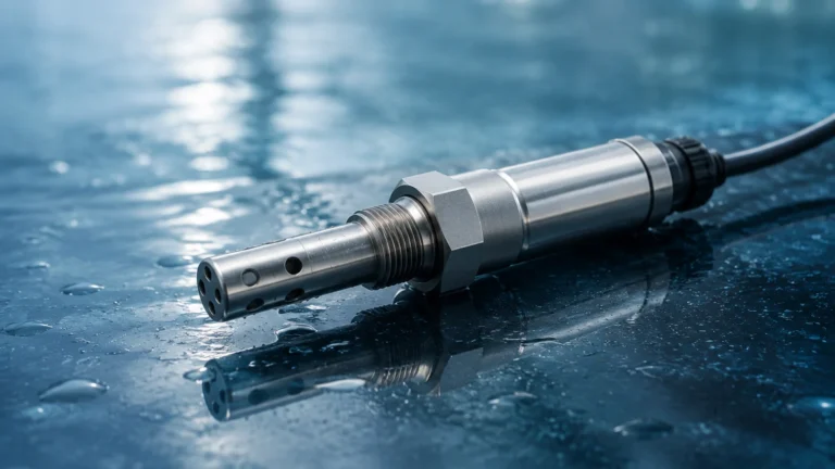
Nozzle Flow Meter
Nozzle Flow Meter
In the landscape of industrial process control, the nozzle flow meter stands as a critical instrument for high-velocity, high-pressure, and high-temperature applications. As a differential pressure (DP) flow measurement device, it offers a robust alternative to orifice plates and a more compact solution than Venturi tubes. For engineers and procurement specialists managing steam circuits, chemical processing, or water treatment facilities, understanding the technical nuances of the nozzle flow meter is essential for ensuring long-term system efficiency and measurement accuracy.
Measurement Principles of the Nozzle Flow Meter
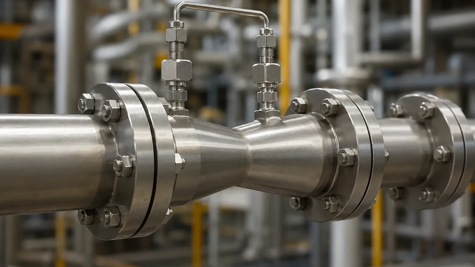
The operation of a nozzle flow meter is rooted in the fundamental laws of fluid mechanics, specifically Bernoulli’s principle and the principle of continuity. When a fluid—whether liquid, gas, or steam—passes through a pipe, its total energy remains constant (assuming no external work or heat transfer).
As the fluid enters the converging section of the flow nozzle, the cross-sectional area of the flow path is reduced. According to the principle of continuity, the velocity of the fluid must increase to maintain a constant mass flow rate. This increase in kinetic energy comes at the expense of static pressure. By measuring the pressure difference between the upstream side of the nozzle and the throat (the narrowest point), the flow rate can be calculated using the following relationship:
1. High-Pressure Zone: Located upstream of the nozzle, where the fluid moves at its normal pipe velocity.
2. Low-Pressure Zone: Located at the nozzle throat, where velocity is at its peak.
3. Differential Pressure (ΔP): The difference between these two points is proportional to the square of the flow rate.
Unlike orifice plates, which have a sharp edge that can erode over time, the nozzle flow meter features a smooth, curved inlet. This profile reduces turbulence and allows for a more predictable discharge coefficient ($C_d$), especially at higher Reynolds numbers. This aerodynamic shape also makes the nozzle more resistant to wear from abrasive particles or high-velocity steam.
Types of Flow Nozzles and Standards
Nozzle flow meters are generally categorized based on their geometry and the international standards they follow. The two most prominent designs used in global industrial applications are the ISA 1932 nozzle and the Long Radius nozzle.
ISA 1932 Nozzle
Standardized under ISO 5167, the ISA 1932 nozzle features a rounded entrance and a cylindrical throat. It is widely used in Europe and international markets for a variety of fluids. It is particularly effective in pipes with diameters ranging from 50 mm to 500 mm. Its geometry is strictly defined to ensure that the discharge coefficient remains stable across a wide range of flow conditions.
Long Radius Nozzle
Commonly designed according to ASME (American Society of Mechanical Engineers) standards, the long radius nozzle is often used in high-velocity steam applications, such as those found in power generation. There are two variations: the high-ratio nozzle (for larger throat-to-pipe diameter ratios) and the low-ratio nozzle. These are preferred when the flow involves high Reynolds numbers where other DP meters might lose accuracy.
Venturi Nozzle
A hybrid design that combines the entrance profile of a standard nozzle with the diverging cone of a Venturi tube. This design aims to provide the accuracy of a nozzle while significantly reducing the permanent pressure loss, making it an energy-efficient choice for large-scale pumping systems.
Technical Selection and Comparison
Choosing the right differential pressure primary element requires a balance between cost, accuracy, and pressure recovery. The following table compares the nozzle flow meter with other common DP elements to assist in the selection process.
| Feature | Orifice Plate | Nozzle Flow Meter | Venturi Tube |
| :— | :— | :— | :— |
| Initial Cost | Low | Medium | High |
| Pressure Loss | High | Medium | Low |
| Accuracy | Good (±1-2%) | Very Good (±0.8-1.5%) | Excellent (±0.5-1%) |
| Erosion Resistance | Poor | Excellent | Excellent |
| Installation Length | Short | Medium | Long |
| Suitability for Solids | Poor | Fair | Good |
| High Velocity Use | Limited | Recommended | Recommended |
For many industrial operators, the nozzle flow meter represents the "middle ground." It is more durable than an orifice plate in high-temperature steam service but significantly less expensive and easier to install than a full-scale Venturi meter. When evaluating options, engineers should consult a comprehensive Main Page of instrumentation to ensure the primary element aligns with the secondary transmitter's capabilities.
Installation and Engineering Considerations
The accuracy of a nozzle flow meter is heavily dependent on the flow profile being fully developed and symmetrical as it enters the device. Improper installation is the leading cause of measurement error in differential pressure systems.
Straight Pipe Requirements
To eliminate swirls and velocity profile distortions caused by elbows, valves, or pumps, a specific length of straight pipe is required both upstream and downstream of the nozzle.
* Upstream: Typically requires 10 to 30 pipe diameters (D) depending on the upstream disturbances.
* Downstream: Usually requires 3 to 7 pipe diameters (D).
If these distances cannot be met due to space constraints, flow conditioners or straighteners must be installed to stabilize the fluid.
Orientation and Tapping
The orientation of the pressure taps depends on the fluid phase:
* Liquids: Taps should be located on the side of the pipe to prevent air bubbles from entering the impulse lines.
* Gases: Taps should be located at the top of the pipe to prevent moisture or condensate from blocking the lines.
* Steam: Taps are usually on the side, with condensate pots used to ensure the impulse lines remain filled with water, protecting the transmitter from high temperatures.
Material Selection
Since nozzle flow meters are often used in aggressive environments, material compatibility is paramount. Standard nozzles are frequently manufactured from 316 Stainless Steel, but for high-temperature steam (above 500°C), Chrome-Moly steels (like P11 or P22) are used to prevent creep and oxidation.
Limitations and Operational Risks
While the nozzle flow meter is a robust instrument, it is not universal. Engineers must be aware of the following limitations:
1. Permanent Pressure Loss: Although lower than an orifice plate, the nozzle still creates a permanent pressure drop in the system. In low-pressure systems, this can lead to increased pumping costs or cavitation in liquid applications.
2. Viscosity Sensitivity: Nozzles are less accurate with highly viscous fluids. They perform best at high Reynolds numbers where inertial forces dominate viscous forces.
3. Installation Complexity: Unlike an orifice plate, which can sometimes be slipped between existing flanges, a flow nozzle often requires a specific housing or a pipe section to be cut and flanged specifically for the nozzle assembly.
4. Non-Linear Output: Like all DP meters, the relationship between flow and pressure is a square root function. This means the meter has a limited turndown ratio (typically 3:1 or 4:1) unless a sophisticated multivariable transmitter is used.
Frequently Asked Questions (FAQ)
Q: Can a nozzle flow meter be used for slurry or fluids with high solids content?
A: While better than an orifice plate due to its smooth sweep, it is generally not recommended for heavy slurries. The solids can accumulate at the upstream face of the nozzle or erode the throat over time. A Venturi meter or an electromagnetic flow meter is usually preferred for such applications.
Q: How often does a flow nozzle need to be calibrated?
A: Flow nozzles are "primary elements," meaning their performance is based on their physical geometry. If the geometry does not change (no erosion or buildup), the calibration remains stable. However, the secondary DP transmitter should be calibrated annually.
Q: What is the difference between a flow nozzle and a flow cone?
A: A flow nozzle constricts the flow from the outside in (converging cone), while a flow cone (like a V-Cone) places a conical element in the center of the pipe. Cones generally require shorter straight pipe runs but can be more complex to size for high-pressure steam.
Conclusion for Project Planning
For industrial projects requiring precise measurement of high-energy fluids, the nozzle flow meter remains a gold standard. Its ability to withstand the erosive forces of high-velocity steam while providing a stable differential pressure signal makes it indispensable in power and heavy process industries.
Before finalizing a specification, project leads should confirm the expected Reynolds number range, the allowable permanent pressure loss, and the available straight pipe run. By selecting a high-quality nozzle from a professional manufacturer like Welk, facilities can ensure long-term reliability and minimize maintenance overhead. For more information on integrating these sensors into a broader automation strategy, engineers are encouraged to review product options and application support on the Main Page.