Nuclear Plant Flow Transmitters
Nuclear Plant Flow Transmitters
In the complex ecosystem of a nuclear power plant (NPP), the precise measurement of fluid dynamics is not merely a matter of operational efficiency; it is a fundamental requirement for reactor safety and structural integrity. Nuclear plant flow transmitters and their associated level measurement instruments provide the critical data necessary to manage primary coolant loops, secondary steam cycles, and auxiliary safety systems. Given the extreme conditions—including ionizing radiation, high pressure, and elevated temperatures—the selection and implementation of these instruments require a rigorous understanding of physics and engineering.
This guide explores the principles behind flow and level measurement in nuclear environments, provides selection criteria for various applications, and outlines the practical considerations for installation and maintenance.
Fundamental Measurement Principles
Before selecting specific instrumentation, it is essential to understand the physical principles that govern flow and level detection in industrial automation. In nuclear applications, these principles are often adapted to ensure redundancy and reliability.
Differential Pressure (DP)
Differential pressure remains the most common principle for both flow and level measurement in NPPs. For flow, a primary element such as an orifice plate, Venturi tube, or flow nozzle creates a restriction in the pipe. According to Bernoulli’s principle, the square root of the pressure drop across this restriction is proportional to the flow rate. For level measurement, hydrostatic pressure is measured at the base of a vessel; the pressure exerted by the liquid column is directly related to its height and density.
Ultrasonic Measurement
Ultrasonic transmitters use sound waves to determine fluid velocity or liquid level.
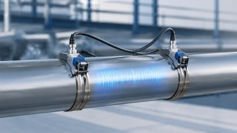
- Transit-Time Flow: Two transducers send and receive ultrasonic pulses. The difference in time taken for the signal to travel upstream versus downstream is used to calculate the flow velocity.
- Non-contact Level: A sensor emits an ultrasonic pulse that reflects off the liquid surface. The time-of-flight determines the distance to the surface. This is ideal for atmospheric tanks where the sensor must remain isolated from the medium.
Radar (Radio Detection and Ranging)
Radar level transmitters, particularly Frequency Modulated Continuous Wave (FMCW) types, emit high-frequency microwave signals. These signals reflect off the product surface and return to the antenna. Radar is highly effective in nuclear applications because it is less affected by temperature fluctuations, vacuum conditions, or high pressure compared to ultrasonic methods.
Electromagnetic Flow Measurement
Electromagnetic flow meters operate based on Faraday’s Law of Electromagnetic Induction. As a conductive fluid (such as cooling water) moves through a magnetic field, it generates a voltage proportional to its velocity. This method is preferred for large-diameter cooling water pipes because it offers no obstruction to the flow and has no moving parts.
Level Measurement Solutions for Nuclear Infrastructure
While flow transmitters monitor the movement of media, level measurement instruments ensure that reservoirs, steam generators, and spent fuel pools maintain the correct volumes. Welk provides a range of industrial instruments that support these auxiliary and balance-of-plant (BOP) processes.
Radar and Ultrasonic Sensors
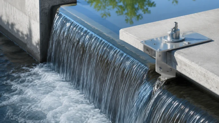
In the secondary loop and water treatment facilities of an NPP, non-contact measurement is preferred to reduce maintenance exposure. Radar level meters are frequently used in chemical storage and condensate tanks due to their high precision (often within ±2 mm). Ultrasonic sensors are more cost-effective for open-channel flow measurement in cooling water discharge or for monitoring large water intake structures.
Hydrostatic and Magnetic Level Gauges
For high-pressure vessels, hydrostatic transmitters offer a robust solution by measuring the head pressure of the liquid. In applications where visual verification is required alongside electronic transmission, magnetic level gauges are employed. These use a float containing a magnet that moves with the liquid level, actuating a visual indicator and providing a 4-20mA signal or switch output for the control room.
For more detailed technical specifications on these technologies, engineers can Review product options and application support at the Welk main site.
Selection Criteria for Nuclear Plant Flow Transmitters
Choosing the right transmitter involves balancing the specific needs of the nuclear environment with the technical capabilities of the sensor. The following table provides a comparison of common technologies used in nuclear plant support systems.
Selection Table: Flow and Level Instrumentation
| Technology | Primary Application | Accuracy | Pressure/Temp Limits | Main Advantage |
| :— | :— | :— | :— | :— |
| DP Transmitter | Steam, Feedwater, Primary Coolant | High (0.075% span) | Very High (up to 400 bar / 600°C) | Industry standard, robust |
| Ultrasonic (Clamp-on) | Cooling Water, Auxiliary Feedwater | Moderate (1-2%) | Limited by pipe material | Non-invasive, no shutdown required |
| Radar Level Meter | Spent Fuel Pool, Chemical Tanks | Excellent (±2mm) | High (up to 160 bar / 450°C) | Unaffected by vapor or density changes |
| Magnetic Level Gauge | Condensate Tanks, Lube Oil | Good | Moderate (up to 100 bar) | Visual redundancy, no power needed for local display |
| Electromagnetic | Raw Water Intake, Wastewater | High (0.5%) | Moderate (PN40) | No pressure drop, handles solids |
Installation and Maintenance Considerations
The installation of nuclear plant flow transmitters must adhere to strict safety codes, often requiring seismic qualification and radiation hardening.
1. Impulse Line Routing: For DP transmitters, the impulse lines (the small pipes connecting the process to the transmitter) must be sloped correctly to prevent gas pockets or sediment buildup. In nuclear steam applications, condensate pots are often required to maintain a constant liquid head.
2. Radiation Shielding: Electronics are sensitive to ionizing radiation. In high-dose areas, the sensing element may be separated from the transmitter electronics by several meters, with the electronics housed in a shielded or lower-radiation zone.
3. Redundancy and Diversity: Safety-critical systems typically use a 2-out-of-3 (2oo3) or 2-out-of-4 (2oo4) voting logic. This requires multiple transmitters using different measurement principles (diversity) to protect against common-cause failures.
4. Material Compatibility: All wetted parts must be compatible with the process fluid. In the primary loop, this usually means high-grade stainless steel (316L) or Inconel to prevent corrosion and the subsequent activation of corrosion products (crude) in the reactor core.

Limitations and Operational Challenges
Despite advancements in technology, nuclear plant flow transmitters face several inherent limitations:
* Signal Drift: Over time, exposure to radiation and high temperatures can cause electronic components to drift. Regular calibration cycles are mandatory, often performed during refueling outages.
* Density Variations: DP-based measurements are sensitive to fluid density. In a nuclear plant, where water may transition from subcooled liquid to superheated steam, sophisticated density compensation algorithms are required in the plant computer or DCS (Distributed Control System).
* Environmental Qualification (EQ): Instruments must be proven to operate during and after a Design Basis Event (DBE), such as a Loss of Coolant Accident (LOCA) or a seismic event. Many standard industrial transmitters do not meet these rigorous EQ requirements without specialized modifications.
* Ambient Temperature Effects: High ambient temperatures in the containment building can affect the accuracy of the transmitter's internal electronics. Active cooling or remote mounting is often necessary.
Frequently Asked Questions (FAQ)
Q: Why is non-invasive flow measurement becoming more popular in nuclear plants?
A: Non-invasive methods, like clamp-on ultrasonic flow meters, allow for measurement without cutting into pipes. This reduces the risk of leaks, maintains the pressure boundary integrity, and allows for the instrumentation of systems that were not originally designed with flow sensors.
Q: How does radiation affect radar level transmitters?
A: While the microwave signal itself is unaffected by radiation, the electronics in the transmitter head can degrade. For high-radiation areas, engineers use "remote-mounted" radar systems where the antenna is in the radiation zone, but the electronics are located behind a biological shield.
Q: What is the difference between a flow transmitter and a flow switch in an NPP?
A: A flow transmitter provides a continuous signal (e.g., 4-20mA or digital bus) representing the actual flow rate. A flow switch is a discrete device that triggers an alarm or action only when the flow crosses a specific threshold (e.g., low-flow trip for pump protection).
Q: Can magnetic level gauges be used in high-radiation zones?
A: Yes. Since the primary indication is mechanical (a magnetic float and flags), it is immune to electronic interference and radiation. However, if a remote transmitter is added to the gauge, that component must be radiation-hardened.
Conclusion
Nuclear plant flow transmitters and level sensors are vital components that bridge the gap between physical process conditions and the control systems that ensure safety. From the robust simplicity of differential pressure to the high-precision capabilities of FMCW radar, each technology has a specific role in the reliable operation of a nuclear facility. By understanding the measurement principles and the unique constraints of the nuclear environment, engineers can select instrumentation that provides long-term accuracy and safety. For professional-grade industrial measurement solutions, including radar, ultrasonic, and magnetic instruments, visit the Welk Main Page to explore technical documentation and product support.