Oil and Gas Flow Meter
Oil and Gas Flow Meter
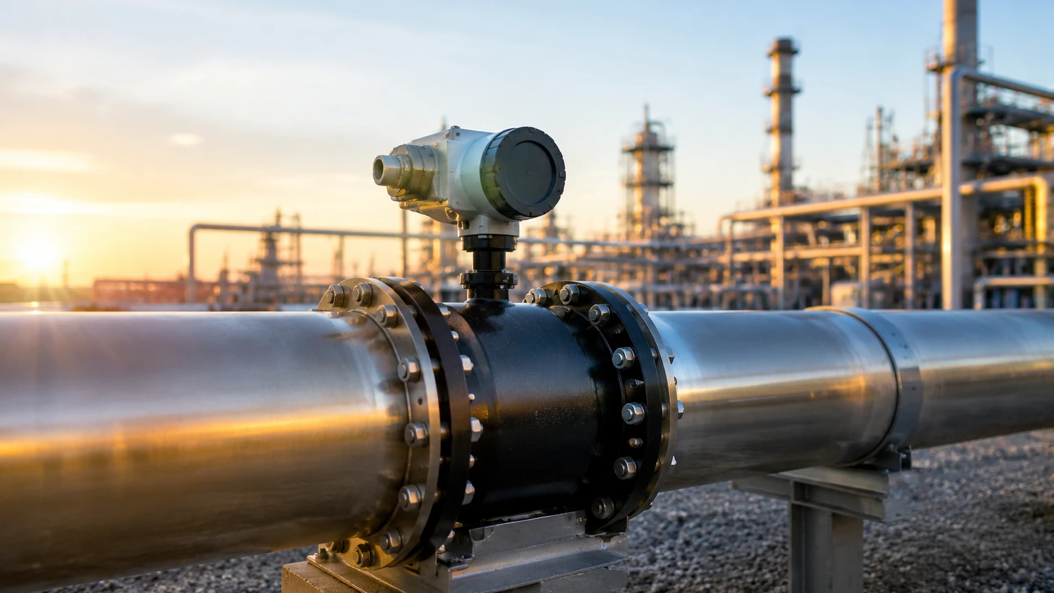
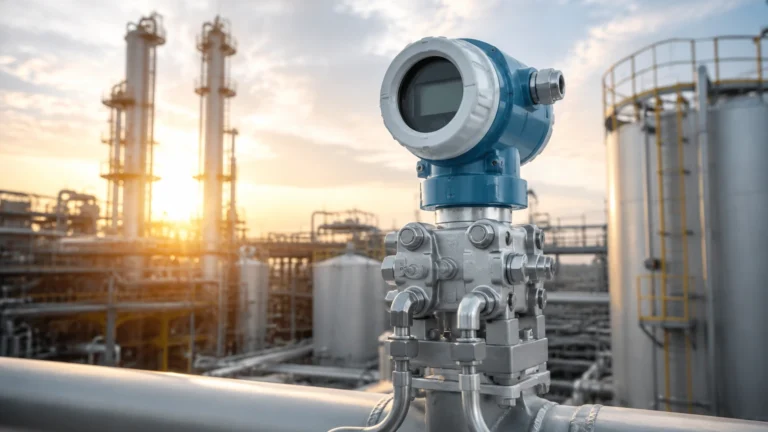
In the complex landscape of industrial process control, the accurate measurement of fluid movement is as critical as monitoring the volume stored within a vessel. An oil and gas flow meter serves as the primary sensory organ for pipelines, refineries, and extraction sites, providing the data necessary for custody transfer, process optimization, and leak detection. While level measurement instruments ensure inventory accuracy in tanks, flow meters manage the dynamic transition of fluids through the production chain. Understanding the interplay between these technologies is essential for any integrated automation system.
Fundamental Principles of Flow Measurement
Before selecting an oil and gas flow meter, it is necessary to understand the physical principles that govern different measurement technologies. Each method interacts with the fluid properties—such as viscosity, density, and Reynolds number—in unique ways.
Coriolis Mass Flow Meters
Coriolis meters operate on the principle of inertia. As fluid flows through an oscillating tube, it causes a slight twist in the tube due to the Coriolis effect. Sensors detect the phase shift between the inlet and outlet oscillations, which is directly proportional to the mass flow rate. These are highly valued in the oil and gas industry because they measure mass directly, independent of changes in fluid density or temperature.
Ultrasonic Flow Meters
In the oil and gas sector, transit-time ultrasonic meters are the standard. They use pairs of transducers to send ultrasonic pulses across the pipe. The time difference between pulses traveling with the flow and those traveling against it is used to calculate velocity. Because they are non-intrusive and have no moving parts, they are ideal for high-pressure natural gas pipelines and large-diameter crude oil lines.
Differential Pressure (DP) Meters
DP meters, such as orifice plates or Venturi tubes, create a deliberate restriction in the flow path. According to Bernoulli’s principle, the pressure drop across this restriction is proportional to the square of the flow velocity. While traditional, these require secondary instrumentation to compensate for temperature and pressure changes to provide accurate mass flow data.
Turbine Flow Meters
Turbine meters utilize a rotor suspended in the fluid stream. The velocity of the fluid causes the rotor to spin at a speed proportional to the flow rate. These are excellent for low-viscosity fluids and high-pressure applications, though they are susceptible to wear if the fluid contains particulates or sand.
Vortex Flow Meters
Vortex meters work on the principle of Von Kármán effect. As fluid passes a "shedder bar," vortices are created. The frequency of these vortices is directly proportional to the flow velocity. These are robust and suitable for steam and gas applications where high reliability is required with minimal maintenance.
Selection Criteria for Oil and Gas Flow Meters
Choosing the correct instrument requires a detailed analysis of the process conditions. The following table provides a comparison of common technologies used in the energy sector.
| Technology | Typical Accuracy | Fluid Type | Turndown Ratio | Maintenance | Primary Advantage |
| :— | :— | :— | :— | :— | :— |
| Coriolis | ±0.1% to 0.2% | Liquid/Gas | 20:1 to 100:1 | Low | Direct mass measurement |
| Ultrasonic | ±0.5% to 1.0% | Liquid/Gas | 50:1 | Low | No pressure drop |
| Turbine | ±0.25% to 0.5% | Clean Liquid | 10:1 | Medium | High repeatability |
| Vortex | ±1.0% | Gas/Steam | 10:1 | Low | Robust in high temps |
| DP (Orifice) | ±1.0% to 2.0% | Liquid/Gas | 3:1 to 4:1 | High | Industry standard/Low cost |
When evaluating these options, engineers must also consider the Main Page of the facility's instrumentation strategy, ensuring that flow data integrates seamlessly with level measurement systems for mass balance calculations.
Key Application Areas in the Energy Sector
The requirements for an oil and gas flow meter vary significantly depending on where in the value chain it is deployed.
* Upstream (Exploration and Production): Meters at the wellhead must handle "multiphase" flow—a mixture of oil, water, and gas. This is one of the most challenging environments, often requiring specialized Coriolis or multiphase meters that can account for varying gas volume fractions.
* Midstream (Transportation and Storage): In pipelines, the priority is custody transfer. Accuracy is paramount here, as even a 0.1% error can result in significant financial discrepancies. Ultrasonic and Coriolis meters are preferred for their precision and reliability over long distances.
* Downstream (Refining and Petrochemicals): Refineries utilize a wide array of meters to manage chemical dosing, steam distribution, and final product loading. Here, the compatibility of the meter with corrosive chemicals and high-temperature fluids is the primary concern.
Installation and Engineering Considerations
Proper installation is as important as the selection of the meter itself. Even the most accurate oil and gas flow meter will fail to perform if the flow profile is disturbed.
1. Straight Pipe Runs: Most velocity-based meters (Turbine, Vortex, DP) require a specific length of straight pipe upstream and downstream to ensure a fully developed, laminar flow profile. Typically, this is 10 to 20 pipe diameters (D) upstream and 5D downstream.
2. Flow Conditioning: If space is limited, flow conditioners or straightening vanes can be installed to eliminate swirl and turbulence caused by elbows, valves, or pumps.
3. Orientation: For liquid applications, the meter should ideally be installed in a vertical line with upward flow to ensure the pipe remains full and to prevent air pockets. For gas applications, horizontal installation is common, with the meter positioned to prevent condensate buildup.
4. Pressure and Temperature Compensation: Since gases are compressible, volumetric flow rates change with pressure and temperature. Integrated systems must include pressure transmitters and RTDs (Resistance Temperature Detectors) to convert actual flow to standard or normal flow units (e.g., Nm³/h).
Technical Limitations and Common Risks
Despite advancements in technology, certain conditions can compromise the integrity of flow measurement:
* Multiphase Interference: Standard liquid meters may fail if gas bubbles are present (slug flow), and gas meters can be damaged by "liquid carryover."
* Abrasive Fluids: In upstream applications, sand and proppants can erode the internal components of turbine meters or the shedder bars of vortex meters.
* Viscosity Shifts: Changes in crude oil temperature significantly alter its viscosity. While Coriolis meters are relatively immune, turbine and DP meters require recalibration or compensation factors to remain accurate.
* Cavitation and Flashing: If the pressure drops below the fluid's vapor pressure within the meter, vapor bubbles form (cavitation). This not only causes measurement errors but can physically pit and destroy the internal surfaces of the instrument.
Integration with Level Measurement Systems
In industrial automation, flow and level measurement are two sides of the same coin. While an oil and gas flow meter measures the rate of change, level sensors (such as radar or ultrasonic transmitters) measure the static state.
For example, in a storage terminal, the flow meter records the volume of oil entering a tank, while the level gauge confirms the total inventory. Discrepancies between the flow meter’s totalizer and the level gauge’s volume calculation are the primary method for detecting leaks or theft. Therefore, it is essential that both types of instruments are calibrated to the same standards and integrated into a unified control system. For those seeking comprehensive solutions in both flow and level monitoring, it is helpful to Review product options and application support to ensure hardware compatibility.
Frequently Asked Questions (FAQs)
Q: How often should an oil and gas flow meter be calibrated?
A: For custody transfer applications, calibration is typically required annually or bi-annually, depending on local regulations and the volume of fluid handled. For process control, every 2 to 3 years is often sufficient unless drift is detected.
Q: Can a single meter measure both liquid and gas?
A: While some Coriolis meters are rated for both, they must be configured differently for each phase. Measuring a mixture of both (multiphase) requires specialized equipment and complex algorithms to provide accurate data for each component.
Q: What is the impact of high pressure on meter selection?
A: High pressure (above 100 bar) necessitates heavy-walled meter bodies and specialized flange ratings (e.g., ANSI 600 or 900). Ultrasonic and Coriolis meters are generally preferred for high-pressure gas because they do not have fragile moving parts that could fail under stress.
Q: Why is mass flow preferred over volumetric flow in oil and gas?
A: Volume changes with temperature and pressure, whereas mass remains constant. Measuring mass provides a more accurate representation of the energy content and the actual amount of product being moved, which is critical for financial transactions.
Conclusion
The selection of an oil and gas flow meter is a foundational decision in process engineering. By understanding the measurement principles—from the phase shifts of Coriolis meters to the transit times of ultrasonic pulses—engineers can mitigate risks associated with fluid properties and environmental conditions. When combined with robust level measurement strategies, these instruments provide the transparency and control required to operate modern energy infrastructure safely and efficiently.