On Site Flow Meter Calibration
On Site Flow Meter Calibration
In industrial process control, the accuracy of flow measurement is paramount for maintaining product quality, ensuring safety, and optimizing operational efficiency. While factory calibration provides a baseline of performance under controlled laboratory conditions, the real-world performance of a flow meter is often influenced by its specific installation environment. This is where on site flow meter calibration becomes a critical engineering practice. By validating the performance of a meter in its actual working environment, engineers can account for piping configurations, fluid dynamics, and environmental variables that a laboratory cannot replicate.
Measurement Principles and Calibration Fundamentals
Before discussing calibration techniques, it is essential to understand the underlying principles of flow measurement. Most industrial flow meters measure either the velocity of the fluid or its mass. Common technologies include electromagnetic meters (Faraday’s Law), ultrasonic meters (transit-time or Doppler shift), and differential pressure meters (Bernoulli’s principle).
Calibration is the process of comparing the readings of a Device Under Test (DUT) against a reference standard with a known, higher accuracy. In a laboratory, this often involves gravimetric systems (weighing the fluid) or volumetric provers. On-site, however, the goal is to verify the "as-installed" accuracy. This is necessary because factors such as upstream elbows, partially closed valves, or internal pipe scaling can distort the flow profile, leading to measurement errors that were not present during the initial factory test.
The Necessity of On Site Flow Meter Calibration
There are several scenarios where on-site validation is preferred or required over laboratory recalibration:
1. System Integrity: Removing a meter for off-site calibration requires breaking the seal of the piping system, which may lead to leaks or contamination risks in sensitive industries like pharmaceuticals or chemical processing.
2. Operational Continuity: Sending a meter to a lab can result in days or weeks of downtime unless a bypass or a spare meter is available.
3. Installation Effects: The "velocity profile" of a fluid is rarely perfectly developed in industrial settings. On-site calibration captures the effects of the specific piping geometry (e.g., 90-degree bends or T-junctions) located immediately upstream of the meter.
4. Regulatory Compliance: Many environmental and fiscal standards require periodic verification of the entire measurement loop, not just the instrument itself.
Primary Methods for On Site Flow Meter Calibration
Several methods are employed to perform calibration without removing the meter from the process line. Each has specific advantages depending on the fluid type and the required precision.
1. Master Meter Method
This is one of the most common techniques for on-site validation. A "master meter"—an instrument with a high degree of precision and a current calibration certificate—is installed in series with the DUT. The readings from both meters are compared across a range of flow rates. It is a standard industry practice that the master meter should be at least three to four times more accurate than the meter being tested.
2. Clamp-On Ultrasonic Verification
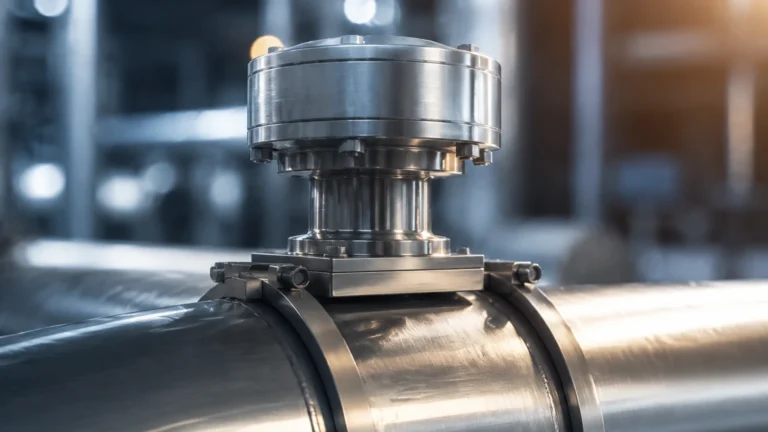
For non-intrusive calibration, clamp-on ultrasonic flow meters are the preferred tool. These devices use transducers strapped to the outside of the pipe to measure flow via transit-time technology. Since they do not require cutting the pipe or stopping the process, they are ideal for quick verification. However, their accuracy is highly dependent on the technician's ability to accurately input the pipe wall thickness, material, and fluid properties.
3. Volumetric or Gravimetric Transfer
In some applications, the fluid passing through the meter can be diverted into a calibrated tank or vessel. By measuring the change in volume or weight over a specific period, the actual flow rate can be calculated and compared to the meter’s output. This is often seen in water treatment and bulk chemical loading stations.
Selection Criteria for Calibration Methods
Choosing the right approach for on site flow meter calibration involves balancing accuracy requirements, budget, and process constraints. The following table provides a comparison of the most frequent methods used in industrial automation.
| Method | Accuracy | Process Interruption | Cost | Best Use Case |
| :— | :— | :— | :— | :— |
| Master Meter | High (0.2% – 0.5%) | Low (if series ports exist) | Moderate | Custody transfer, high-value fluids |
| Clamp-on Ultrasonic | Moderate (1.0% – 2.0%) | None | Low | General process check, large pipes |
| Volumetric Transfer | Very High (0.1%) | High (requires diversion) | High | Tank loading, chemical dosing |
| Insertion Probe | Moderate (2.0% – 3.0%) | Moderate (requires hot tap) | Moderate | Large diameter air/gas ducts |
Installation Considerations and Technical Boundaries
To ensure a successful calibration, certain physical and hydraulic conditions must be met. Failure to adhere to these guidelines can render the calibration data invalid.
Straight Pipe Requirements
Most flow meters require a specific length of straight pipe both upstream and downstream to ensure a stable, non-turbulent flow profile. A common rule of thumb is 10 diameters (10D) of straight pipe upstream and 5 diameters (5D) downstream. If the on-site installation does not meet these requirements, the calibration must be performed at the actual operating flow rates to "map" the error caused by the turbulence.
Reynolds Number and Fluid Properties
The Reynolds number (Re) characterizes the flow regime as laminar, transitional, or turbulent. Calibration should ideally be performed at the same Reynolds number as the normal operating conditions. Changes in fluid viscosity or density—often caused by temperature fluctuations—can significantly shift the meter's K-factor (pulses per unit volume).
Environmental Factors
On-site conditions are rarely as stable as a laboratory. Ambient temperature swings, vibration from nearby pumps, and electromagnetic interference (EMI) from variable frequency drives (VFDs) can affect the electronics of both the DUT and the reference standard. Technicians must use shielded cabling and, where possible, perform calibration during periods of stable ambient conditions.
Limitations and Potential Risks
While on-site calibration is highly beneficial, it is not without limitations. One of the primary risks is the "uncertainty budget." In a lab, every variable is controlled. On-site, the uncertainty of the reference meter is compounded by the uncertainty of the installation itself.
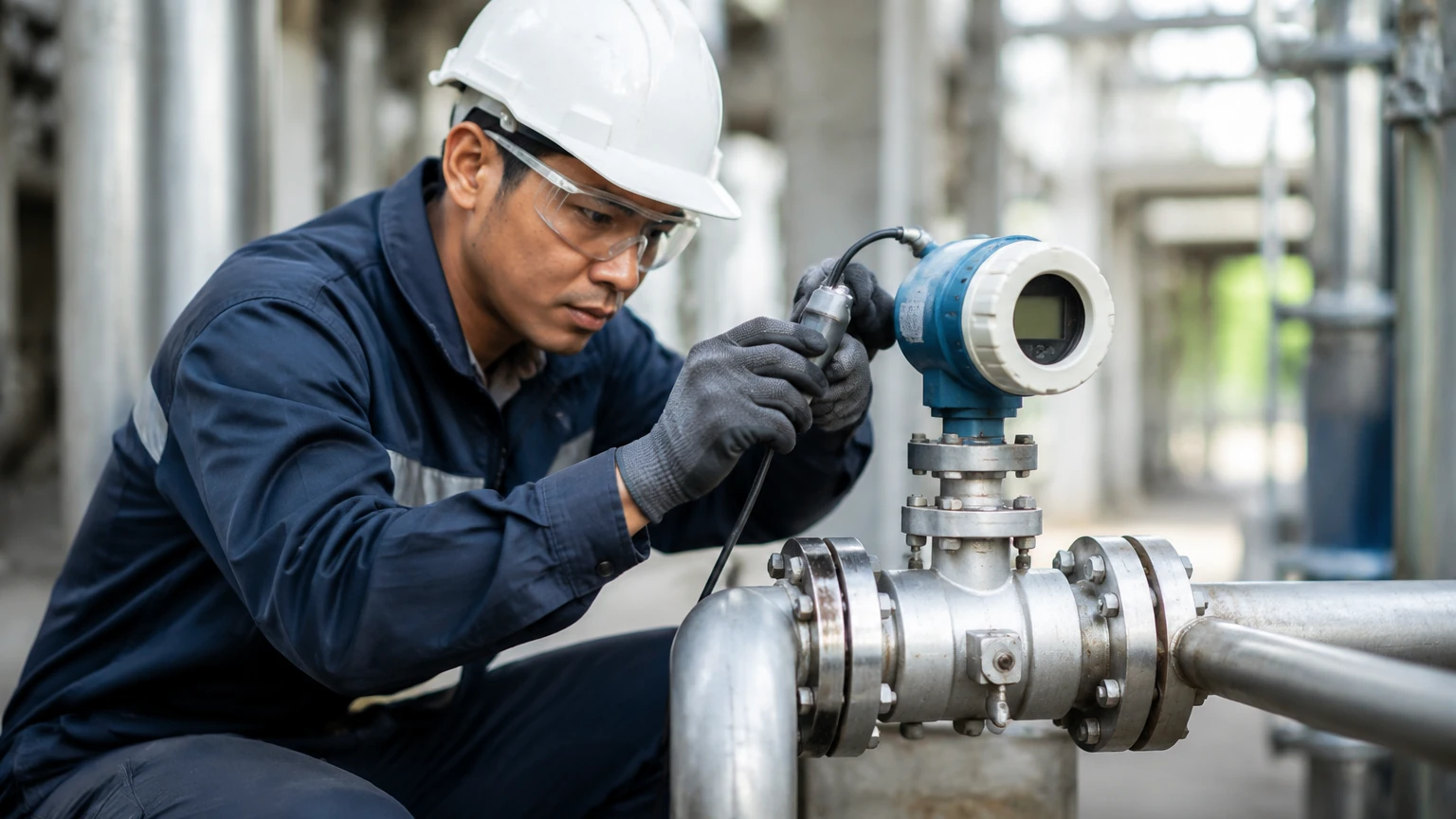
Furthermore, safety is a major concern. Calibration often involves working near high-pressure lines or hazardous chemicals. Proper Personal Protective Equipment (PPE) and adherence to Lockout/Tagout (LOTO) procedures are mandatory. If a master meter must be installed in-line, the system must be depressurized and drained, which introduces the risk of air entrapment upon restart—a common cause of measurement error in electromagnetic and ultrasonic meters.
Integrating Level and Flow Measurement
In many industrial applications, flow measurement and level measurement are deeply interconnected. For instance, in open channel flow (common in wastewater treatment), the flow rate is often calculated by measuring the level of liquid as it passes through a flume or weir. In these cases, a high-precision ultrasonic or radar level sensor is used as the primary measuring element.
Reliable instruments, such as those found on the Welk Main Page, play a vital role in these integrated systems. When performing on site flow meter calibration for an open channel, the technician is essentially calibrating the level-to-flow conversion formula. Ensuring the level transmitter is accurately zeroed and calibrated is the first step in ensuring the flow data is correct.
Similarly, in tank inventory management, hydrostatic level transmitters are used to calculate the mass of the liquid in the tank. If the tank is being filled via a flow meter, comparing the change in the tank's calculated mass (derived from level and density) against the flow meter's totalizer is a practical form of "indirect" on-site calibration.
Step-by-Step Calibration Procedure
A standardized approach ensures repeatability and traceability. A typical on-site calibration event follows these steps:
1. Pre-Test Inspection: Check the meter for physical damage, leaks, or loose wiring. Verify that the pipe is full (for liquid applications).
2. Reference Setup: Install the master meter or clamp-on transducers according to the manufacturer’s specifications, ensuring proper acoustic coupling for ultrasonic units.
3. Zero Verification: With the flow completely stopped and the pipe full, verify that both the DUT and the reference meter read zero.
4. Multi-Point Testing: Run the process at a minimum of three flow rates (e.g., 25%, 50%, and 75% of maximum flow). Allow the flow to stabilize at each point before recording data.
5. Data Analysis: Calculate the error percentage at each point. If the error exceeds the allowable tolerance, adjustments to the meter’s K-factor or scaling may be necessary.
6. Documentation: Issue a calibration report including the serial numbers of all equipment used, the environmental conditions, the traceability of the reference standard, and the "as-found" and "as-left" data.
Frequently Asked Questions (FAQ)
Q: How often should on site flow meter calibration be performed?
A: This depends on the criticality of the process and regulatory requirements. Most industrial plants perform calibration annually, though high-accuracy custody transfer applications may require quarterly verification.
Q: Can I calibrate a gas flow meter using the same methods as a liquid meter?
A: The principles are similar, but gas calibration is more complex due to the compressibility of the fluid. Pressure and temperature compensation are mandatory for gas flow calibration to convert actual flow to standard flow (e.g., Nm³/h).
Q: What is the difference between calibration and validation?
A: Calibration involves comparing a device against a standard and making adjustments if necessary. Validation (or verification) is the process of simply checking if the device is still within its specified accuracy limits without necessarily making adjustments.
Q: Why does my clamp-on meter show a different reading than my in-line meter?
A: This is often due to incorrect pipe wall thickness settings or the presence of internal scale/corrosion in the pipe, which changes the internal diameter and affects the velocity calculation of the ultrasonic signal.
Q: Is on-site calibration as accurate as laboratory calibration?
A: Generally, no. Laboratory environments eliminate most external variables, allowing for much lower uncertainty. However, on-site calibration is often more "realistic" because it accounts for the specific hydraulic conditions of the installation.
Conclusion
On site flow meter calibration is an indispensable tool for the modern process engineer. It bridges the gap between theoretical factory accuracy and practical field performance. By understanding the measurement principles and selecting the appropriate verification method, facilities can ensure their flow systems remain accurate, compliant, and efficient. Whether using master meters for high-precision chemical dosing or leveraging level measurement technologies from the Main Page for open channel flow, a robust calibration program is the foundation of reliable industrial automation.