Electrfication
Electrfication
In the modern industrial landscape, the transition from mechanical monitoring to digital precision is often defined by the broad process of electrfication. For process engineers and facility managers, this shift represents more than just a change in power source; it is a fundamental evolution in how data is gathered, processed, and utilized to ensure operational safety and efficiency. In the realm of level measurement, electrfication has replaced manual sounding tapes and simple float-and-pulley systems with sophisticated sensors capable of sub-millimeter accuracy and real-time remote communication.
This guide explores the technical foundations of electronic level measurement, the principles governing modern sensors, and the practical considerations for integrating these technologies into industrial automation frameworks. By understanding the nuances of electronic instrumentation, organizations can better navigate the complexities of modernizing their liquid and solid storage assets.
The Evolution of Level Measurement through Electrfication
Historically, level measurement relied heavily on physical interaction with the medium or mechanical indicators that required frequent manual inspection. While functional, these systems were prone to wear, required significant maintenance, and offered no way to integrate data into a centralized Control Room or Distributed Control System (DCS).
The electrfication of these processes began with simple limit switches and has progressed to continuous measurement technologies that utilize electromagnetic waves, sound, and pressure. Today, the integration of microprocessors into level transmitters allows for advanced signal processing, such as false-echo suppression and automatic temperature compensation. This digital transformation enables facilities to move toward "Industry 4.0," where every tank and silo becomes a data point in a networked ecosystem.
For those looking to upgrade their current infrastructure, it is essential to Review product options and application support on the Welk Main Page to identify which electronic solutions align with specific process requirements.
Core Measurement Principles in Electronic Systems
Before selecting a device, it is critical to understand the physics behind how electronic level meters interpret the distance or volume of a medium. Most modern industrial sensors fall into three primary categories: Radar, Ultrasonic, and Hydrostatic.
1. Radar Level Measurement (ToF and FMCW)
Radar level meters represent the pinnacle of electronic level sensing. They operate using high-frequency electromagnetic waves, typically in the 26 GHz or 80 GHz range.
* Pulse Radar (Time of Flight): The sensor emits a short microwave pulse that travels to the surface of the medium, reflects, and returns to the receiver. The electronics measure the time it takes for the pulse to travel the round trip. Since the speed of light is constant, the distance is calculated as: *Distance = (Speed of Light × Time) / 2*.
* FMCW (Frequency Modulated Continuous Wave): Instead of pulses, the sensor emits a continuous signal with a constantly changing frequency. The difference in frequency between the emitted and received signal is proportional to the distance. FMCW is generally more accurate and provides better signal-to-noise ratios in turbulent conditions.
2. Ultrasonic Level Measurement
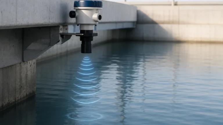
Ultrasonic sensors utilize sound waves rather than electromagnetic waves. A piezoelectric crystal inside the sensor head converts electrical energy into mechanical vibrations (sound pulses). These pulses bounce off the liquid surface and return to the sensor.
Because the speed of sound is affected by air temperature, most high-quality ultrasonic meters include an integrated temperature sensor to recalibrate the distance calculation in real-time. This technology is highly effective for water treatment and open-channel flow but can struggle in vacuum conditions or where heavy foam is present, as sound requires a medium (air/gas) to travel.
3. Hydrostatic Level Measurement
Hydrostatic transmitters measure the pressure exerted by a liquid column at a specific point, usually the bottom of the tank. The principle is based on Pascal’s Law, which states that the pressure at the bottom of a liquid column is directly proportional to its height and density.
* Formula: *P = ρ × g × h*
* *P* = Hydrostatic Pressure
* *ρ* = Density of the liquid
* *g* = Gravitational constant
* *h* = Height of the liquid
By converting this pressure into an electrical signal (typically 4-20mA), the system can determine the exact level regardless of the tank’s shape, provided the density remains constant.
Technical Selection Criteria for Electrified Level Sensors
Choosing the right technology requires a detailed analysis of the process environment. The following table provides a comparison of common electronic level measurement technologies used in industrial electrification projects.
| Technology | Typical Accuracy | Media Type | Max Temperature | Pressure Range | Key Advantage |
| :— | :— | :— | :— | :— | :— |
| 80GHz Radar | ±1 mm to ±2 mm | Liquids & Solids | Up to +250°C | Up to 160 bar | Non-contact, ignores steam/dust |
| Ultrasonic | ±0.25% of Range | Liquids & Slurries | Up to +80°C | Up to 3 bar | Cost-effective, easy setup |
| Hydrostatic | ±0.1% to ±0.5% | Clean Liquids | Up to +100°C | N/A (Submersible) | Ideal for deep wells and vented tanks |
| Guided Wave Radar | ±2 mm | Liquids/Interfaces | Up to +400°C | Up to 400 bar | Works in high turbulence/foam |
| Magnetic Gauge | ±5 mm (Visual) | Hazardous Liquids | Up to +400°C | Up to 320 bar | Redundant visual + electronic output |
Infrastructure Requirements and Signal Integration
The process of electrfication involves more than just mounting a sensor; it requires a robust electrical infrastructure to power the device and transmit its data.
Power Supply Configurations
* 2-Wire (Loop Powered): The most common configuration in modern plants. Both the power and the 4-20mA signal share the same pair of wires. This significantly reduces wiring costs and simplifies installation in hazardous areas.
* 4-Wire: Separate pairs for power (e.g., 24VDC or 110/220VAC) and signal. These are typically used for high-power devices like long-range radar or units with integrated heaters for cold climates.
Digital Communication Protocols
Modern electronic level meters rarely provide just a simple analog signal. To fully leverage the benefits of electrfication, sensors often utilize digital overlays:
* HART (Highway Addressable Remote Transducer): Allows digital communication to be superimposed on the 4-20mA analog signal, enabling remote configuration and diagnostics.
* Modbus RTU / RS485: Common in water treatment and smaller automation projects for multi-drop networking.
* Profibus/Foundation Fieldbus: Used in large-scale industrial plants for high-speed, bi-directional data exchange.

Installation and Commissioning Best Practices
To ensure the longevity and accuracy of an electrified level system, strict adherence to installation guidelines is mandatory. Electronic components are sensitive to environmental factors and improper mounting.
1. Avoid Internal Obstructions: For radar and ultrasonic sensors, the signal beam must have a clear path to the surface. Avoid mounting the sensor near agitators, ladders, or inflow pipes. If obstructions are unavoidable, use software-based "False Echo Suppression" to map out the static interference.
2. Dead Zone Management: Every electronic sensor has a "blocking distance" or dead zone near the sensor face where measurement is impossible. Ensure the sensor is mounted high enough that the maximum liquid level never enters this zone.
3. Cable Shielding and Grounding: To prevent Electromagnetic Interference (EMI) from variable frequency drives (VFDs) and motors, use shielded cables. The shield should typically be grounded at only one end (usually the control cabinet) to avoid ground loops.
4. Environmental Protection: In outdoor installations, use sunshades to prevent the electronics from overheating and ensure that cable glands are pointing downwards to prevent moisture ingress (using a drip loop).
Operational Limitations and Environmental Factors
While electrification provides significant advantages, electronic sensors are not universal solutions. Engineers must be aware of specific limitations:
* Dielectric Constant (εr): Radar sensors rely on the reflectivity of the medium. Materials with very low dielectric constants (like certain oils or liquefied gases) may reflect a weak signal, requiring high-sensitivity radar or guided-wave radar.
* Vapor and Dust: High-frequency radar (80GHz) can penetrate heavy dust and steam, but ultrasonic waves are often absorbed or scattered by these conditions, leading to signal loss.
* Power Stability: Unlike mechanical gauges, electronic transmitters require stable power. Voltage spikes or brownouts can cause signal drift or damage the internal microprocessors. The use of surge protection is highly recommended in regions with unstable power grids.
Frequently Asked Questions (FAQ)
Q: Can I replace a mechanical float gauge with an electronic radar meter directly?
A: Yes, in most cases. However, you must ensure that the tank nozzle size is compatible with the radar's antenna and that there is a power source available for the new transmitter.
Q: How does electrification contribute to plant safety?
A: Electronic sensors allow for redundant high-level alarms and SIL (Safety Integrity Level) ratings. They eliminate the need for operators to climb tanks for manual measurements, reducing the risk of falls and exposure to hazardous vapors.
Q: Is calibration required for electronic level meters?
A: Most modern sensors are factory-calibrated. However, "field calibration" is usually required to define the zero and span points relative to the specific tank geometry. Periodic verification is recommended to account for any sensor drift over time.
Q: What is the impact of foam on electronic measurement?
A: Foam can be a challenge. Thick, dense foam may absorb ultrasonic signals. Radar is generally more effective, but for extremely heavy foam, a guided wave radar (GWR) or a hydrostatic transmitter is often the more reliable choice.
Conclusion
The ongoing electrfication of industrial processes has transformed level measurement from a manual task into a precise, automated science. By selecting the appropriate measurement principle—whether it be the non-contact precision of radar, the versatility of ultrasonic, or the rugged reliability of hydrostatic pressure—facilities can achieve unprecedented levels of accuracy and safety. As technology continues to advance, the integration of these electronic systems into broader data networks will remain a cornerstone of modern industrial efficiency.