Ultrasonic Flow Meter
Ultrasonic Flow Meter
In the landscape of industrial process control, the ultrasonic flow meter has emerged as a cornerstone technology for non-invasive and highly accurate liquid measurement. Unlike traditional mechanical meters that rely on moving parts—which are prone to wear, pressure drops, and maintenance issues—ultrasonic technology utilizes sound waves to determine the velocity of a fluid within a closed conduit. As industries move toward more automated and maintenance-free operations, understanding the nuances of ultrasonic flow measurement is essential for process engineers and facility managers.
This guide provides a technical overview of ultrasonic flow measurement principles, selection criteria, and practical installation strategies to ensure long-term reliability in demanding environments.
Understanding Ultrasonic Flow Measurement Principles
Ultrasonic flow meters operate based on the physics of acoustic wave propagation. There are two primary methods used in industrial applications: Transit-Time and Doppler Effect. Selecting the correct principle is the first and most critical step in instrument specification.
Transit-Time Method
Transit-time ultrasonic flow meters are the most common for clean liquid applications. This method uses a pair of transducers, each acting as both a transmitter and a receiver. The transducers are mounted on the pipe, and ultrasonic signals are pulsed alternately between them.
When the fluid is moving, the signal traveling in the direction of the flow (downstream) moves faster than the signal traveling against the flow (upstream). The meter measures this time difference ($Δt$) with nanosecond precision. The flow velocity ($v$) is directly proportional to this time difference.
Mathematically, this is expressed as:
$$v = K · Δt / t_{avg}^2$$
Where $K$ is a calibration factor and $t_{avg}$ is the average transit time. This technology is highly effective for water, oils, and chemicals where the liquid is relatively free of suspended solids or entrained air.
Doppler Effect Method
The Doppler method relies on the frequency shift of a sound wave reflected off moving discontinuities within the liquid, such as suspended particles or aerated bubbles. A transducer emits an ultrasonic signal of a known frequency. If the fluid contains reflectors moving at a certain velocity, the reflected signal will return at a different frequency.
While transit-time meters require clean fluids, Doppler meters *require* a minimum concentration of particles or bubbles (typically at least 100 parts per million of 75-micron sized particles) to function. This makes them ideal for wastewater, slurries, and aerated liquids where transit-time signals would be scattered or absorbed.
Types of Ultrasonic Flow Meters
Beyond the measurement principle, ultrasonic flow meters are categorized by their physical construction and mounting method.
1. Clamp-on Ultrasonic Flow Meters
Clamp-on meters are mounted on the exterior of the pipe. They offer the significant advantage of non-intrusive measurement, meaning the process does not need to be shut down for installation, and there is no risk of leakage or contamination. These are favored in the chemical and pharmaceutical industries where maintaining the integrity of the piping system is paramount.
2. Inline (Wetted) Ultrasonic Flow Meters
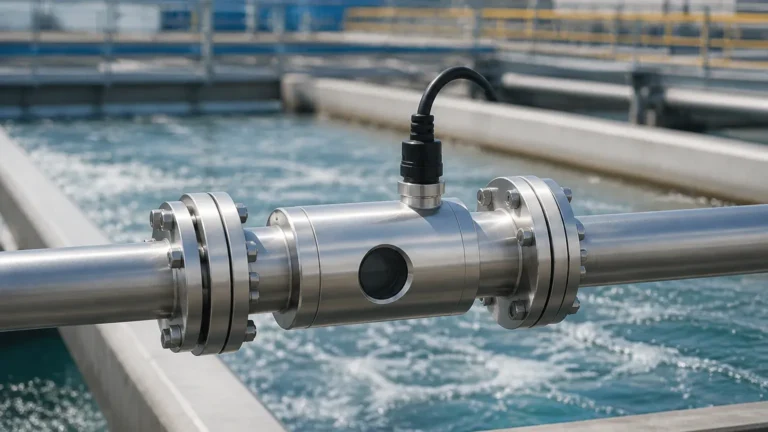
Inline meters involve a specialized pipe section with factory-installed ultrasonic transducers. Because the transducers are in direct contact with the fluid (or protected by a thin buffer), the signal path is precisely defined. This generally results in higher accuracy (often ±0.5% of reading or better) compared to clamp-on models. These are common in custody transfer and high-precision industrial automation.
Selection Criteria and Technical Specifications
When evaluating an ultrasonic flow meter for a specific project, engineers must consider the fluid properties, pipe material, and environmental conditions. The following table provides a general selection framework for industrial applications.
| Feature | Transit-Time (Clamp-on) | Transit-Time (Inline) | Doppler Effect |
| :— | :— | :— | :— |
| Fluid Type | Clean liquids, low turbidity | Clean liquids | Slurries, aerated liquids |
| Typical Accuracy | ±1% to ±2% of velocity | ±0.5% of velocity | ±2% to ±5% of full scale |
| Pipe Size Range | 15 mm to 6000 mm | 15 mm to 1000 mm | 25 mm to 3000 mm |
| Installation Cost | Low (No pipe cutting) | Moderate to High | Low (No pipe cutting) |
| Pressure Drop | Zero | Negligible | Zero |
| Maintenance | Very Low | Low | Moderate (Sensor cleaning) |
For complex industrial automation setups, it is often beneficial to consult a professional manufacturer. Companies like Welk provide a range of instruments, from radar level meters to ultrasonic sensors, ensuring that the entire measurement loop is compatible. Reviewing product options and application support on the Main Page can help in identifying the specific model required for your pipe schedule and fluid profile.
Installation and Maintenance Considerations
The performance of an ultrasonic flow meter is heavily dependent on the installation environment. Even the most advanced meter will provide inaccurate data if the flow profile is disturbed.
Straight Pipe Requirements
To achieve a stable, fully developed flow profile, the meter must be installed in a straight section of pipe. The standard engineering rule is "10D Upstream and 5D Downstream." This means there should be a straight pipe length equal to 10 times the pipe diameter before the meter and 5 times the diameter after it. If there are pumps or high-turbulence valves upstream, the requirement may increase to 20D or 30D.
Transducer Mounting Methods (Clamp-on)
For clamp-on installations, three primary mounting configurations are used depending on pipe size and fluid attenuation:
* V-Method: The signal bounces once off the opposite pipe wall. This is the standard for pipes ranging from 25 mm to 400 mm (1 to 16 inches).
* Z-Method: The transducers are placed on opposite sides of the pipe, and the signal crosses the pipe once. This is used for large pipes or highly attenuative fluids where the signal might be too weak for a bounce.
* W-Method: The signal bounces three times. This is reserved for very small pipes (below 50 mm) to increase the transit time and improve resolution.
Acoustic Coupling
For clamp-on meters, the air gap between the transducer and the pipe wall must be eliminated. A specialized acoustic coupling grease or permanent adhesive is used. In outdoor or high-temperature environments, this couplant can dry out over years, requiring periodic inspection and re-application to maintain signal strength.

Limitations and Application Risks
While ultrasonic flow meters are versatile, they are not universal solutions. Engineers should be aware of the following limitations:
1. Pipe Material and Liners: Ultrasonic waves travel differently through different materials. While carbon steel, stainless steel, and PVC are excellent conductors, pipes with internal liners (like cement or loose plastic liners) can create an air gap that reflects the signal, rendering the meter inoperable.
2. Reynolds Number: Ultrasonic meters are calibrated for specific flow regimes (laminar or turbulent). If the flow is in the "transition zone" (Reynolds number between 2,000 and 4,000), accuracy may fluctuate.
3. Aeration and Solids: In transit-time meters, excessive bubbles or solids (typically >2% by volume) will scatter the ultrasonic beam. If your process involves significant entrained air, a Doppler-style meter or a different technology like electromagnetic flow measurement may be required.
4. Temperature Limits: Standard transducers typically handle up to 120°C (248°F). High-temperature applications require specialized transducers with heat sinks or wave-guide technology.
Industrial Applications and Case Use
Water and Wastewater Management
In municipal water treatment, ultrasonic flow meters are used for leak detection and pump efficiency monitoring. Their ability to measure large-diameter pipes (up to 6000 mm) without the cost of massive mechanical meters makes them the primary choice for main distribution lines.
Chemical Processing
Because clamp-on ultrasonic meters do not touch the fluid, they are ideal for measuring corrosive acids, bases, and high-purity chemicals. This eliminates the risk of chemical attack on the sensor and prevents the sensor from contaminating the product.
Oil and Gas
In the petrochemical sector, these meters are used for measuring refined products and lubricating oils. The transit-time method provides the high repeatability necessary for process optimization, while the lack of moving parts ensures safety in volatile environments.
Frequently Asked Questions (FAQs)
Q: Can an ultrasonic flow meter measure gas flow?
A: Yes, but it requires specialized high-frequency transducers and high-power electronics because gases are much less dense than liquids, making acoustic transmission more difficult. Standard liquid ultrasonic meters cannot be used for gas.
Q: Does the pipe need to be full?
A: Yes, for accurate measurement, the pipe must be completely full of liquid. If the pipe is partially full, the ultrasonic signal will be reflected by the air-liquid interface, leading to errors. In gravity-fed systems, the meter should be installed at a low point (a "U" trap) to ensure the pipe remains full.
Q: How often do ultrasonic flow meters need calibration?
A: Since there are no moving parts to wear out, the electronic calibration is very stable. However, in regulated industries, an annual or biennial verification is standard. For clamp-on meters, this can often be done in-situ using a master meter for comparison.
Q: Can it measure flow in both directions?
A: Yes, most modern transit-time ultrasonic flow meters are inherently bidirectional. They can distinguish between forward and reverse flow and provide separate totals for each.
Conclusion
The ultrasonic flow meter represents a sophisticated blend of acoustic physics and digital signal processing, offering a reliable, non-intrusive solution for modern industrial flow measurement. By understanding the distinction between transit-time and Doppler principles and adhering to strict installation guidelines—specifically regarding straight pipe runs and acoustic coupling—operators can achieve high-precision data with minimal maintenance overhead.
Whether you are managing a water treatment facility, a chemical plant, or an oil refinery, selecting the right instrumentation is key to operational efficiency. For those integrating flow measurement with level control systems, exploring the comprehensive range of sensors available on the Main Page ensures a unified approach to process automation and monitoring.