Permanent Clamp on Flow Meter
Permanent Clamp on Flow Meter
In modern industrial process control, the ability to measure fluid flow without interrupting operations or compromising the integrity of piping systems has become a critical requirement. A permanent clamp on flow meter represents a sophisticated solution for long-term flow monitoring, utilizing ultrasonic technology to provide accurate data from the exterior of a pipe. Unlike traditional inline meters that require cutting pipes, installing flanges, and risking potential leak points, clamp-on systems offer a non-invasive alternative that maintains the hydraulic profile of the system.
For engineers and facility managers, the transition from portable diagnostic tools to permanent clamp-on installations is driven by the need for continuous data integration into SCADA or PLC systems. This guide examines the technical foundations, selection criteria, and installation protocols necessary to ensure the long-term reliability of these instruments in industrial environments.
Understanding the Measurement Principle
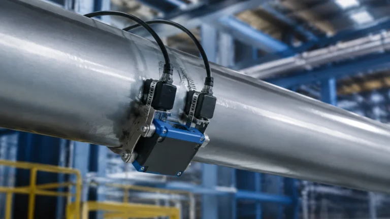
Most permanent clamp on flow meters operate on the transit-time ultrasonic principle. This method relies on the physics of sound propagation within a moving fluid. The system typically consists of a pair of transducers mounted on the outside of the pipe at a specific distance from each other.
Transit-Time Difference
The transducers function as both transmitters and receivers of ultrasonic pulses. One transducer sends a signal diagonally through the pipe wall and the fluid to the second transducer. The second transducer then sends a return signal to the first. When the fluid is moving, the pulse traveling in the direction of the flow (downstream) moves faster than the pulse traveling against the flow (upstream).
The meter electronics calculate the time difference ($Δt$) between these two signals. This time difference is directly proportional to the velocity of the fluid. By incorporating the known internal diameter of the pipe and the cross-sectional area, the meter converts the velocity into a volumetric flow rate (e.g., cubic meters per hour or liters per minute).
Signal Correlation and Processing
Modern permanent installations utilize advanced digital signal processing (DSP) to filter out background noise caused by industrial machinery or pipe vibrations. This ensures that the "time-of-flight" measurement remains stable even in electrically noisy environments. Because the sound must travel through the pipe wall, the coupling between the transducer and the pipe surface is a critical component of the measurement circuit.
Why Choose a Permanent Clamp on Flow Meter?
The decision to specify a permanent clamp-on system over an electromagnetic or vortex meter often hinges on total cost of ownership (TCO) and process safety.
Non-Invasive Advantages
Because the sensors never touch the process fluid, there is no risk of chemical corrosion or mechanical wear on the meter components. This is particularly advantageous for aggressive chemicals, ultra-pure water, or high-pressure systems where a leak could be catastrophic. Furthermore, because there are no internal obstructions, the meter creates zero pressure drop, which can lead to significant energy savings in pumping costs over the lifetime of the installation.
Installation Without Downtime
One of the most compelling reasons for selecting a permanent clamp on flow meter is the ability to install the unit while the process is running. There is no need to drain the pipes or halt production. This makes it an ideal choice for retrofitting existing facilities where the cost of a plant shutdown would far exceed the cost of the instrumentation itself.
For comprehensive process monitoring, these flow solutions are often paired with advanced level measurement technologies to provide a full picture of mass balance and inventory. Engineers looking for integrated solutions can Review product options and application support to understand how flow and level data work in tandem for automated tank management.
Key Selection Criteria for Engineering Projects
Selecting the correct permanent clamp on flow meter requires a detailed analysis of the application environment. Unlike inline meters, the performance of a clamp-on meter is heavily dependent on the pipe's physical properties.
Pipe Material and Condition
Ultrasonic signals travel differently through various materials. Standard materials like carbon steel, stainless steel, and PVC are excellent conductors of ultrasonic energy. However, pipes with internal liners (such as rubber, glass, or cement) present a challenge. If the liner is not perfectly bonded to the host pipe, an air gap can exist, which will completely block the ultrasonic signal.
Fluid Characteristics
Transit-time meters are designed for "clean" liquids. While they can tolerate a small percentage of suspended solids or entrained air bubbles (typically less than 2% to 5% by volume), excessive aeration will scatter the sound waves and cause a loss of signal. For slurries or highly aerated liquids, a Doppler-style meter may be more appropriate, though these are less common for high-precision permanent installations.
Selection Table: Application Suitability
| Parameter | Preferred Range | Limitations |
| :— | :— | :— |
| Pipe Size | DN15 to DN6000 (0.5" to 240") | Very small pipes (<15mm) require specialized fixtures. |
| Pipe Material | Carbon Steel, Stainless, PVC, Copper | Ductile iron or lined pipes require high-power transducers. |
| Fluid Velocity | 0.5 m/s to 12 m/s | Accuracy drops significantly below 0.3 m/s. |
| Temperature | -40°C to +150°C | High-temp applications (>200°C) require specialized stand-offs. |
| Fluid Type | Water, Oils, Chemicals, Glycol | Not suitable for gases or high-concentration slurries. |
Installation Best Practices and Transducer Mounting
The accuracy of a permanent clamp on flow meter is almost entirely dependent on the quality of the installation. Even the most expensive electronics cannot compensate for poorly mounted transducers.
Straight Pipe Requirements
To ensure a stable and repeatable flow profile, the meter must be installed in a section of straight pipe. The industry standard is typically 10 diameters (10D) of straight pipe upstream of the sensors and 5 diameters (5D) downstream. If the installation is near a pump or a partially open valve, these requirements may increase to 20D or 30D to allow turbulence to subside.
Mounting Methods (V, Z, and W Paths)
There are three primary ways to mount the transducers, depending on the pipe size and fluid properties:
1. V-Method: The most common method for pipes ranging from DN50 to DN400. The signal crosses the pipe, reflects off the opposite wall, and returns to the second transducer. This doubles the path length, increasing the time resolution and accuracy.
2. Z-Method: Used for large pipes (typically >DN400) or where the fluid is slightly attenuative. The transducers are mounted on opposite sides of the pipe, and the signal crosses only once.
3. W-Method: Used for very small pipes (DN15 to DN50). The signal reflects three times, creating a very long path length to capture measurable time differences in small volumes.
Pipe Preparation and Coupling
Before mounting, the pipe surface must be cleaned of all rust, scale, and loose paint. A smooth, flat surface is required for the transducer to make contact. Because air is a poor conductor of ultrasound, a coupling agent (grease or gel) is applied between the transducer face and the pipe. For permanent installations, high-viscosity silicone grease or solid foil pads are used to ensure the acoustic bond does not dry out over time.
Technical Limitations and Application Risks
While highly versatile, permanent clamp on flow meters are not a universal solution. Engineers must be aware of specific risks that can degrade performance over several years of operation.
* Scaling and Fouling: If the interior of the pipe develops a layer of scale (common in hard water applications), the internal diameter changes. Since the meter calculates flow based on the programmed diameter, this will lead to a systematic overestimation of flow. Furthermore, thick scale can attenuate the signal.
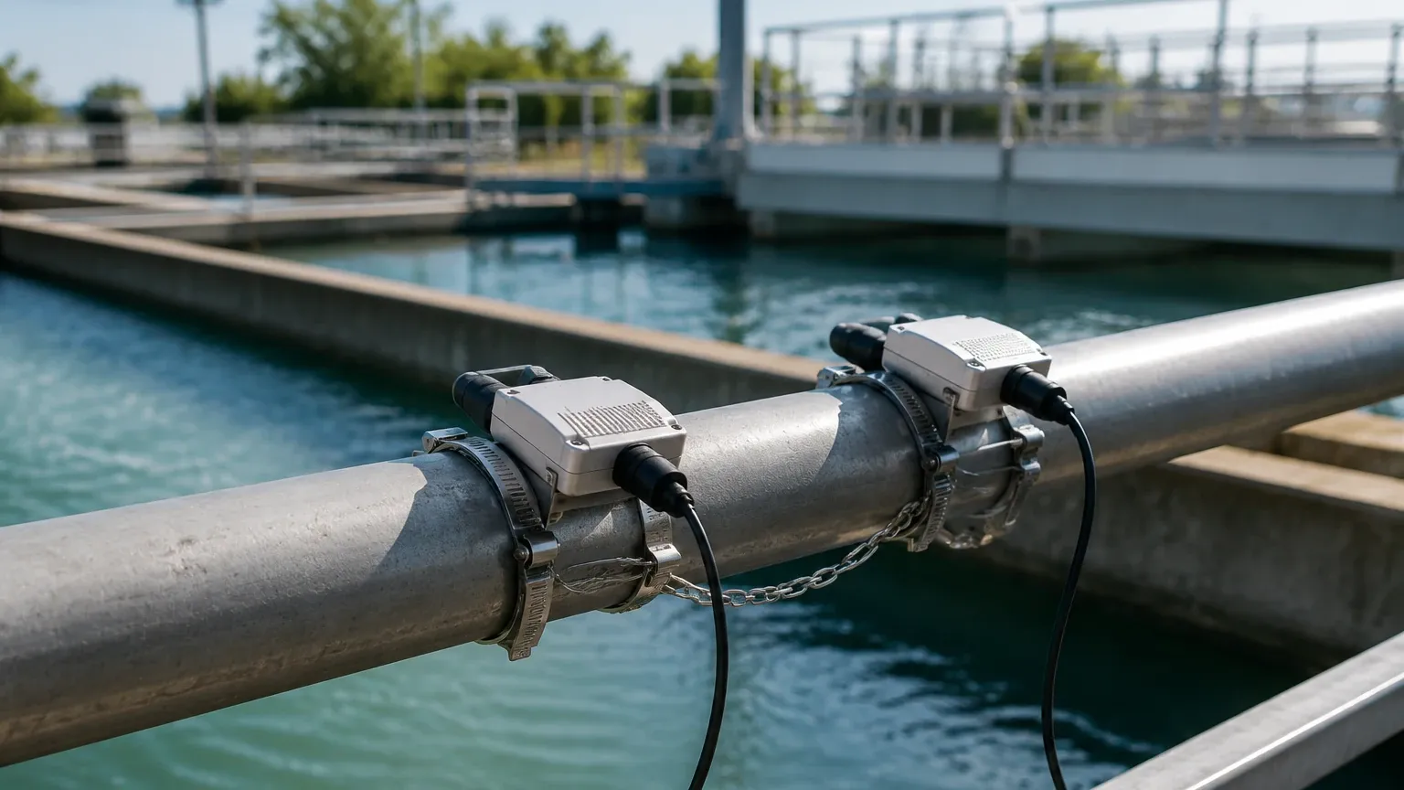
* Coupling Degradation: In high-temperature applications or outdoor environments with extreme thermal cycling, the coupling grease can eventually migrate or dry out. This results in a "Signal Strength" alarm. For permanent installs, using a dedicated mounting track with spring-loaded tensioners is recommended to maintain constant pressure.
* Wall Thickness Uncertainty: The accuracy of the transit-time calculation depends on knowing the exact wall thickness of the pipe. In older facilities, pipe wall thinning due to corrosion can introduce errors. It is best practice to use an ultrasonic thickness gauge to verify the pipe dimensions before commissioning the flow meter.
Maintenance and Long-Term Reliability
A permanent clamp on flow meter is generally considered low-maintenance because it has no moving parts. However, a routine inspection schedule should be established to ensure continued accuracy.
1. Signal Strength Monitoring: Most modern transmitters provide a signal-to-noise ratio (SNR) or signal strength percentage. A drop in this value over time usually indicates a need for re-greasing or a change in fluid conditions.
2. Zero-Flow Calibration: Whenever the process can be stopped and the pipe remains full, a zero-point calibration should be performed. This eliminates any small electronic offsets that may have drifted.
3. Cable Integrity: In permanent outdoor installations, the cables between the transducers and the transmitter should be protected by conduit to prevent damage from UV exposure or rodents.
Comparison: Clamp-on vs. Inline Technologies
| Feature | Clamp-on Ultrasonic | Electromagnetic (Magmeter) | Vortex Shedding |
| :— | :— | :— | :— |
| Installation | External (No cutting) | Inline (Flanged) | Inline (Flanged) |
| Pressure Drop | Zero | Zero (Full bore) | Moderate |
| Conductivity | Independent | Requires >5 μS/cm | Independent |
| Moving Parts | None | None | None |
| Maintenance | Low (External) | Low (Internal) | Moderate (Sensor fouling) |
| Initial Cost | Moderate to High | Low to Moderate | Moderate |
Frequently Asked Questions (FAQs)
Q: Can a clamp-on flow meter measure flow through a pipe with an air gap in the liner?
No. Ultrasonic waves cannot pass through air gaps. If a liner is delaminated or if there is an air pocket between the pipe and the liner, the signal will be reflected back, and the meter will fail to provide a reading.
Q: How accurate are permanent clamp-on meters compared to inline meters?
Under ideal conditions (correct pipe parameters and sufficient straight runs), a permanent clamp-on meter can achieve accuracies of ±0.5% to ±1% of flow rate. While some high-end inline magmeters can achieve ±0.25%, the difference is often negligible for most industrial process applications.
Q: Does the pipe material affect the measurement?
Yes. The meter must be programmed with the correct longitudinal sound speed for the pipe material. Materials like plastic attenuate the signal more than metals, which may require the use of lower-frequency transducers for thicker plastic walls.
Q: Is it possible to use a clamp-on meter on vertical pipes?
Yes, provided the flow is moving upward. Upward flow ensures the pipe remains completely full. Downward flow in a vertical pipe can result in partial filling or vacuum pockets, which will prevent the meter from functioning correctly.
By following these engineering principles and installation guidelines, a permanent clamp on flow meter can provide decades of reliable service. Whether used in water treatment, chemical processing, or HVAC energy monitoring, these instruments offer a balance of performance and logistical simplicity that is difficult to match with invasive technologies. For those managing complex liquid systems, integrating these flow insights with reliable level data from the Main Page ensures a robust and efficient industrial operation.