Flow Transmitter Unit
Flow Transmitter Unit
In the landscape of industrial process control, the flow transmitter unit serves as a critical sensory component, providing the real-time data necessary for automation, safety, and efficiency. While level measurement determines the volume or height of a medium within a vessel, flow measurement tracks the rate at which that medium moves through a system. For engineers and plant managers, selecting the correct flow transmitter unit requires a deep understanding of fluid dynamics, sensor technology, and the specific environmental constraints of the application.
Industrial flow measurement is not a one-size-fits-all discipline. Whether managing water treatment facilities, chemical processing plants, or oil and gas refineries, the choice of a flow transmitter unit directly impacts the accuracy of mass balance calculations and the reliability of the entire control loop. Organizations looking to optimize their measurement infrastructure often consult the Main Page of specialized manufacturers like Welk to compare various instrumentation technologies.
Measurement Principles of Flow Transmitter Units
Before selecting a flow transmitter unit, it is essential to understand the physical principles that govern how these devices interpret fluid movement. Most modern units consist of two primary parts: the primary element (the sensor that interacts with the fluid) and the secondary element (the transmitter that converts the sensor's signal into a standardized output, such as 4-20mA or Modbus).
Electromagnetic Principle (Faraday’s Law)
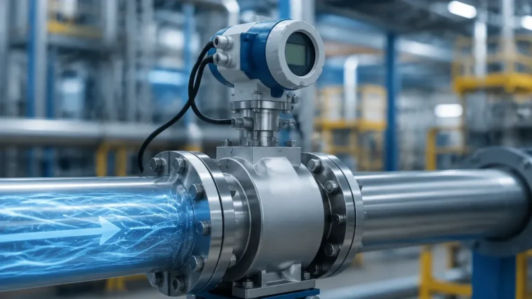
Electromagnetic flow transmitter units are widely used for conductive liquids. They operate based on Faraday’s Law of Induction, which states that a voltage is induced when a conductive fluid moves through a magnetic field. The unit generates a magnetic field across the pipe diameter; as the liquid flows, it creates a voltage proportional to its velocity. Because there are no moving parts or obstructions in the flow path, these units offer low pressure drop and high reliability for slurries and corrosive chemicals.
Ultrasonic Principle (Transit-Time and Doppler)
Ultrasonic units are favored for their non-invasive nature.
1. Transit-Time: These units use two transducers that send and receive ultrasonic pulses. The time difference between the pulse traveling with the flow and the pulse traveling against the flow is used to calculate velocity. This is ideal for clean liquids.
2. Doppler Effect: These units reflect sound waves off particles or bubbles in the fluid. The frequency shift of the reflected wave indicates the flow speed. This is preferred for aerated liquids or fluids with suspended solids.
Differential Pressure (Bernoulli’s Principle)
Differential pressure (DP) flow transmitter units utilize a primary element, such as an orifice plate or Venturi tube, to create a constriction in the pipe. According to Bernoulli’s principle, this constriction causes a pressure drop. The transmitter measures the pressure difference between the upstream and downstream sides, which is proportional to the square of the flow rate. While traditional, these units remain a staple in steam and high-pressure gas applications.
Vortex Shedding
Vortex flowmeters operate on the Karman Vortex Street principle. As fluid flows past a "bluff body" (an obstruction) placed in the pipe, vortices are shed alternately on each side. The frequency of these vortices is directly proportional to the fluid velocity. These units are highly robust and suitable for high-temperature steam and low-viscosity liquids.
Practical Selection Criteria
Choosing the right flow transmitter unit involves balancing technical requirements with budget constraints. The following table provides a general guideline for technology selection based on common industrial media.
| Fluid Type | Recommended Technology | Conductivity Requirement | Typical Accuracy | Pressure Drop |
| :— | :— | :— | :— | :— |
| Potable Water | Electromagnetic | > 5 μS/cm | ±0.5% | Negligible |
| Deionized Water | Ultrasonic (Transit-Time) | Not Required | ±1.0% | None |
| Sulfuric Acid | Electromagnetic (PTFE Lined) | High | ±0.5% | Negligible |
| Saturated Steam | Vortex | Not Required | ±1.5% | Moderate |
| Crude Oil | Ultrasonic or DP | Not Required | ±1.0% | Variable |
Fluid Properties
The chemical compatibility of the wetted parts is paramount. For corrosive media, the flow transmitter unit must feature liners (such as PTFE or PFA) and electrodes (such as Tantalum or Hastelloy) that can withstand the process conditions. Furthermore, the viscosity of the fluid can dictate the technology; for instance, electromagnetic meters are unaffected by viscosity changes, whereas DP meters require Reynolds number corrections.
Pipe Size and Flow Range
Units are typically sized based on flow velocity rather than pipe diameter. A common engineering mistake is matching the meter size to the existing pipe size without checking the minimum and maximum flow rates (turndown ratio). Most electromagnetic units perform best at velocities between 0.5 m/s and 10 m/s (1.6 ft/s to 32.8 ft/s).
Installation and Commissioning Considerations
The accuracy of a flow transmitter unit is heavily dependent on its installation environment. Even the most precise instrument will provide erroneous data if the flow profile is distorted by turbulence.
Straight Pipe Requirements
To ensure a fully developed flow profile, most flow transmitter units require a specific length of straight pipe upstream and downstream of the sensor. A standard rule of thumb is "10D Upstream and 5D Downstream," where D is the nominal pipe diameter. If a pump or a partially closed valve is located immediately before the unit, the upstream requirement may increase to 20D or 40D to allow turbulence to subside.
Mounting Orientation
* Horizontal Pipes: For liquid applications, the pipe must remain full at all times. The transmitter should be installed in a section of the pipe that is lower than the rest of the system to prevent air pockets. In electromagnetic units, electrodes should be positioned horizontally (at 3 o'clock and 9 o'clock) to prevent interference from sediment at the bottom or air at the top.
* Vertical Pipes: Flow should ideally move upward. This ensures the pipe remains full and prevents the fluid from "falling" through the meter, which would cause significant measurement errors.
Grounding and Shielding
In electromagnetic flow transmitter units, proper grounding is essential to eliminate stray electrical noise. The fluid, the sensor, and the transmitter must be at the same electrical potential. If the piping is plastic or lined, grounding rings must be installed to establish a conductive path to the medium. Signal cables should be shielded and kept away from high-voltage power lines to prevent electromagnetic interference (EMI).
Integration with Level Measurement Systems
In many industrial setups, flow transmitter units work in tandem with level sensors to provide a comprehensive view of a process. For example, in a chemical blending tank, a radar level meter monitors the total volume, while flow transmitter units on the inlet and outlet pipes track the rate of addition and extraction. This dual-monitoring approach allows for:
* Mass Balance Verification: Comparing the integrated flow data against the change in level to detect leaks or sensor drift.
* Redundancy: Providing a secondary means of calculating volume in critical safety applications.
* Pump Control: Using flow data to prevent pump cavitation when tank levels are low.
Welk provides a range of level measurement solutions that are designed to integrate seamlessly with standard industrial flow transmitter units via 4-20mA or digital protocols, ensuring that plant operators have a unified data stream for their automation systems.
Limitations and Common Risks
While modern flow transmitter units are highly advanced, they are not immune to failure or inaccuracy. Engineers should be aware of the following risks:
1. Entrained Air: In liquid flow measurement, bubbles can cause significant over-reading in electromagnetic meters or signal loss in ultrasonic meters. Air eliminators should be installed if the process is prone to aeration.
2. Scaling and Buildup: In wastewater or chemical applications, coatings can form on the electrodes or the inner walls of the sensor. This changes the effective diameter of the pipe and insulates the electrodes, leading to drift. Regular inspection or the use of units with "electrode cleaning" functions is recommended.
3. Low Flow Cut-off: Most units have a minimum threshold below which they cannot accurately measure. If the process operates frequently at very low velocities, a smaller meter or a different technology (like a positive displacement meter) may be necessary.
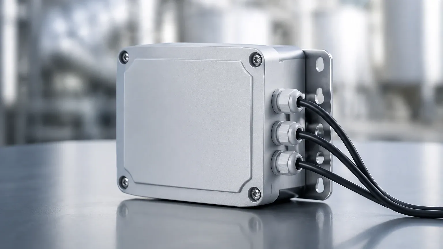
4. Environmental Factors: High ambient temperatures or extreme vibration can damage the transmitter electronics. In such cases, a "remote mount" configuration is preferred, where the sensor is in the process line and the transmitter unit is mounted in a more stable environment.
Maintenance and Calibration
To maintain the integrity of the data, flow transmitter units require periodic verification. Many modern units feature internal self-diagnostics that can check the health of the coils, electrodes, and circuitry without removing the device from the line. However, for regulatory compliance or high-precision applications, wet calibration at a certified laboratory remains the gold standard.
Typically, a calibration interval of 12 to 24 months is sufficient for clean water applications, while abrasive or corrosive media may require semi-annual checks. Documentation of these calibrations is vital for ISO quality standards and environmental reporting.
Frequently Asked Questions (FAQ)
Q: Can a flow transmitter unit measure both directions of flow?
A: Yes, many electromagnetic and ultrasonic units are inherently bi-directional. They can be configured to provide separate totals for forward and reverse flow, which is useful in distribution networks or tank loading/unloading operations.
Q: What is the difference between a flow sensor and a flow transmitter?
A: The flow sensor (or primary element) is the part that physically interacts with the fluid to generate a raw signal. The flow transmitter (secondary element) processes that signal, applies calibration factors, and outputs a standardized signal for the control system.
Q: How do I handle flow measurement in a pipe that is not always full?
A: Standard flow transmitter units require a full pipe to provide accurate readings. If the pipe is partially full, specialized "partially full" electromagnetic meters or area-velocity ultrasonic sensors must be used.
Q: Does the pressure of the liquid affect the flow transmitter unit?
A: For most liquid applications, pressure has a negligible effect on the measurement. However, for gas and steam, pressure and temperature must be compensated for because these fluids are compressible. In these cases, a multivariable transmitter is often used.
By carefully evaluating the measurement principles, installation requirements, and fluid characteristics, engineering teams can select a flow transmitter unit that ensures long-term operational stability. For those seeking integrated solutions for both level and flow, exploring the technical resources available on the Main Page can provide the necessary guidance for complex industrial applications.