Pipe Thermowell
Pipe Thermowell
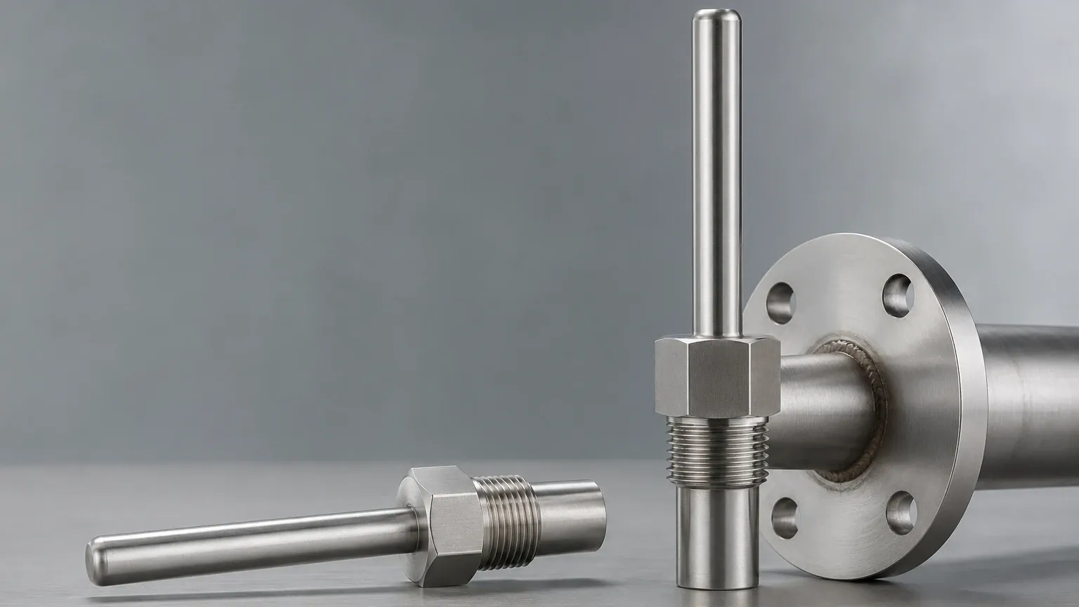
In industrial process control, the accuracy of temperature measurement is as critical as the protection of the instruments themselves. A pipe thermowell is a cylindrical fitting designed to protect temperature sensors—such as RTDs (Resistance Temperature Detectors), thermocouples, and bimetal thermometers—from the harsh conditions within a piping system. By acting as a pressure-tight barrier, the thermowell allows the sensor to be removed or replaced without breaking the process seal or stopping the flow.
For engineers managing complex systems, understanding the mechanical and thermal principles of thermowells is essential. This guide explores the design, selection, and installation of pipe thermowells, with a specific focus on their role in supporting accurate level measurement and industrial automation.
Principles of Operation and Thermal Transfer
A pipe thermowell functions as a heat exchanger. Its primary purpose is to conduct thermal energy from the process fluid to the sensing element located inside the well's bore. To achieve this, the thermowell must balance two conflicting requirements: mechanical strength and thermal responsiveness.
Heat Conduction
When a thermowell is inserted into a pipe, the process fluid transfers heat to the outer surface of the well via convection. This heat then travels through the wall of the thermowell via conduction to reach the internal sensor. The efficiency of this transfer depends on the thermal conductivity of the material and the thickness of the wall. Thinner walls provide faster response times but offer less resistance to high pressures and abrasive media.
Pressure Containment
From a mechanical perspective, the thermowell is a pressure vessel. It must withstand the static pressure of the system and the dynamic forces of the fluid flow. In high-velocity applications, the fluid creates a wake behind the thermowell, leading to vortex shedding. If the frequency of this shedding matches the natural frequency of the thermowell, mechanical resonance occurs, which can lead to catastrophic fatigue failure.
Classification of Pipe Thermowells by Mounting Type
The method by which a thermowell is attached to a pipe significantly impacts its pressure rating, ease of maintenance, and suitability for specific industries. The following table summarizes the common mounting configurations used in industrial piping.
Selection Table: Thermowell Mounting Types
| Mounting Type | Pressure Rating | Maintenance Ease | Typical Applications |
| :— | :— | :— | :— |
| Threaded | Low to Medium | High (Easy removal) | Water treatment, HVAC, non-corrosive utilities |
| Flanged | High | Medium | Oil & Gas, Chemical processing, Petrochemical |
| Socket Weld | Very High | Low (Permanent) | High-pressure steam, hazardous chemicals |
| Weld-in | Highest | Very Low | Power plants, critical high-pressure lines |
| Sanitary (Clamp) | Low | Very High | Food and beverage, Pharmaceutical |
Threaded Thermowells
These are screwed into a threaded pipe tee or a weldolet. They are cost-effective and easy to replace but are generally limited to non-hazardous applications where minor leaks at the threads are not a critical safety risk. Standard thread sizes include 1/2", 3/4", and 1" NPT.
Flanged Thermowells
Flanged versions are bolted to a mating flange on the piping. This design is preferred for high-pressure and highly corrosive environments because it provides a robust, leak-proof seal. They are also easier to inspect than welded versions. Common flange ratings include ANSI/ASME Class 150, 300, and 600.
Welded Thermowells
Socket weld and weld-in thermowells are used where a permanent, leak-proof connection is mandatory. These are common in high-velocity steam lines and applications involving toxic or lethal fluids where any risk of a threaded or flanged leak must be eliminated.
Material Selection and Chemical Compatibility
The longevity of a pipe thermowell is dictated by its resistance to corrosion and erosion. While Stainless Steel 316 (SS316) is the industry standard for general-purpose applications, specialized processes require more exotic alloys.
1. Stainless Steel 304/316: Offers excellent corrosion resistance for water, steam, and mild chemicals. SS316 is preferred for its superior resistance to chlorides and pitting.
2. Monel 400: Ideal for applications involving sea water, hydrofluoric acid, and sulfuric acid.
3. Hastelloy C-276: A high-performance nickel alloy used in extremely aggressive chemical environments, including wet chlorine gas and ferric chlorides.
4. Inconel 600: Best suited for high-temperature applications where oxidation resistance is required, such as furnace exhausts.
When selecting materials, engineers must also consider the "Stem Profile." Straight stems are standard, tapered stems offer a higher natural frequency to resist flow-induced vibration, and stepped stems provide the fastest thermal response by reducing the mass at the tip.
Engineering Considerations: Wake Frequency and Mechanical Stress
The most common cause of thermowell failure is not pressure, but vibration. As fluid flows past the thermowell, it creates alternating low-pressure vortices. This phenomenon, known as the Von Kármán effect, induces oscillations.
ASME PTC 19.3 TW Standard
The American Society of Mechanical Engineers (ASME) established the PTC 19.3 TW standard to provide a rigorous calculation method for thermowell design. This standard evaluates:
* Frequency Ratio: The ratio of the wake frequency to the thermowell's natural frequency must be less than 0.8 to avoid resonance.
* Static Stress: The ability of the material to withstand the process pressure at operating temperature.
* Dynamic Stress: The stress caused by the cyclic forces of vortex shedding.
* Hydrostatic Pressure: Ensuring the tip thickness is sufficient to prevent collapse.
If a thermowell fails these calculations, engineers may need to reduce the immersion length, increase the root diameter, or switch from a straight to a tapered profile.
The Role of Temperature in Level Measurement Accuracy
While thermowells are primary temperature instruments, they play a vital supporting role in industrial level measurement. Many level sensing technologies are dependent on temperature data to maintain accuracy.
For instance, ultrasonic level sensors calculate distance based on the speed of sound. However, the speed of sound varies significantly with air temperature. Without accurate temperature compensation—often provided by an auxiliary sensor in a pipe thermowell near the tank inlet—the level reading can drift by several percentage points. Similarly, hydrostatic level transmitters measure the pressure exerted by a liquid column. Since liquid density changes with temperature, a temperature measurement is required to convert pressure into an accurate volume or level reading.
In chemical and oil applications, where thermal expansion can alter the volume of stored liquids, integrating temperature and level data is essential for inventory management. For those seeking comprehensive measurement arrays, you can Review product options and application support to see how integrated sensing solutions optimize process efficiency.
Installation Best Practices for Piping Systems
Correct installation is critical to ensure that the thermowell provides a representative temperature reading of the process fluid.
Immersion Depth
As a general rule, the sensitive portion of the sensor (the tip) should be located in the middle third of the pipe. For pipes smaller than 100 mm (4 inches), the thermowell is often installed in an elbow or at an angle to ensure sufficient immersion length. Insufficient immersion leads to "conduction error," where the ambient temperature outside the pipe influences the reading because heat is conducted away from the sensor tip through the thermowell body.
* Liquid flows: Minimum immersion should be 8 to 10 times the thermowell tip diameter.
* Gas/Steam flows: Minimum immersion should be 10 to 15 times the tip diameter.
Orientation
* Perpendicular: The most common installation, suitable for large pipes with moderate flow velocities.
* Elbow Installation: The thermowell is installed in a pipe bend, pointing upstream. This allows for a longer immersion length in small-diameter pipes and reduces the impact of flow-induced vibration.
* Acute Angle: Installing at a 45-degree angle against the flow can also increase immersion length in restricted spaces.
Insulation
To minimize thermal lag and conduction errors, the portion of the thermowell extending outside the pipe (the "lagging extension") should be insulated along with the pipe itself. This ensures the thermowell remains at the same temperature as the process fluid.
Limitations, Risks, and Maintenance
Despite their robustness, pipe thermowells have limitations that must be addressed during the design phase:
* Thermal Lag: The mass of the thermowell introduces a delay in temperature sensing. In processes with rapid temperature fluctuations, this lag can hinder real-time control. Using a stepped stem or a heat-conductive paste inside the bore can mitigate this.
* Erosion: In slurries or high-velocity particulate flows, the leading edge of the thermowell can wear down over time. Hard-facing coatings (like Tungsten Carbide) are often applied to extend service life.
* Bore Contamination: Moisture or debris inside the thermowell bore can cause sensor corrosion or erratic readings. Always ensure the sensor transition is properly sealed with a weather-proof head.
Maintenance Checklist
1. Visual Inspection: Check for signs of erosion, pitting, or bending during scheduled shutdowns.
2. Wake Frequency Review: If process flow rates are increased (de-bottlenecking), re-calculate the wake frequency to ensure the existing thermowell is still safe.
3. Sensor Calibration: Periodically remove the internal sensor for calibration. The thermowell itself does not require calibration, but its internal bore should be checked for oxidation.
Frequently Asked Questions (FAQs)
Q: What is the difference between "U" length and "T" length in a thermowell?
A: The "U" length (immersion length) is the distance from the mounting point to the tip of the thermowell. The "T" length (lagging extension) is the distance between the mounting point and the instrument connection, usually used to allow for pipe insulation.
Q: Can I use a thermowell in a pipe smaller than 2 inches?
A: Yes, but a standard perpendicular installation may block too much of the flow path. In these cases, it is best to use a pipe tee or an elbow installation to provide enough room for the thermowell without causing a significant pressure drop.
Q: How do I choose between a tapered and a straight stem?
A: Use a straight stem for low-velocity applications where cost is a factor. Use a tapered stem for high-velocity applications (above 5 m/s for liquids or 30 m/s for gases) to increase the mechanical strength and natural frequency of the well.
Q: Does the thermowell material need to match the pipe material?
A: Generally, yes. Matching the material avoids galvanic corrosion and ensures that the thermal expansion coefficients are similar, which is particularly important for welded installations.
By following these engineering guidelines and adhering to standards like ASME PTC 19.3 TW, process engineers can ensure that their pipe thermowells provide reliable protection and accurate data for both temperature and level control systems.