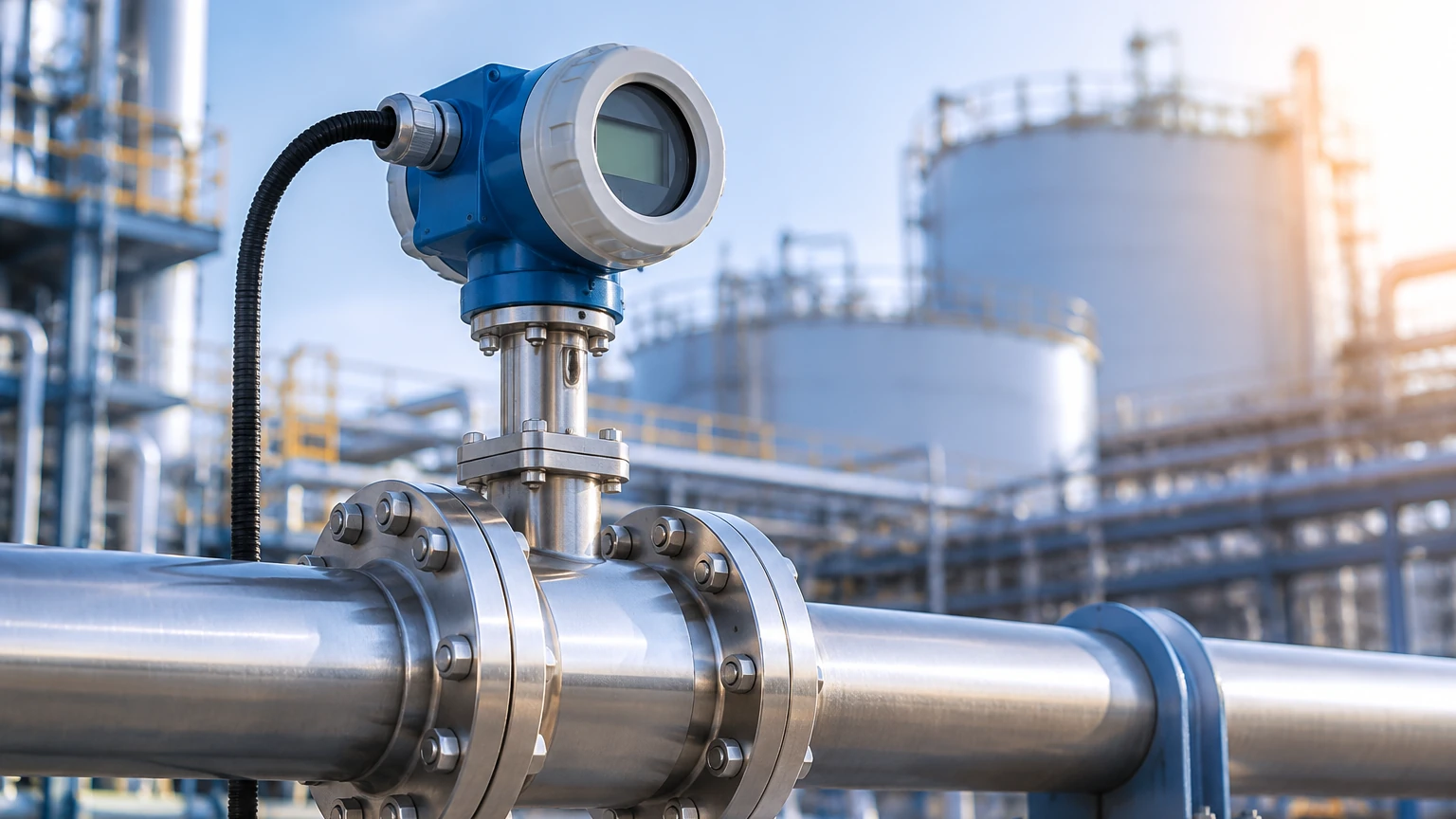
Pressure Compensated Flow Meter
Pressure Compensated Flow Meter
In industrial process control, the accuracy of fluid measurement is often compromised by the physical properties of the media being measured. For gases, steam, and certain high-pressure liquids, volume is not a static value; it fluctuates significantly based on environmental conditions. A pressure compensated flow meter is an essential instrument used to correct these volumetric variations by integrating real-time pressure and temperature data. This ensures that the flow rate is reported in standardized units or mass units, providing the precision required for custody transfer, chemical dosing, and energy management.
Understanding the Measurement Principles
To understand why a pressure compensated flow meter is necessary, one must first look at the behavior of compressible fluids. Unlike most liquids, which are relatively incompressible, the density of gases and steam is highly dependent on the operating pressure and temperature.
The Ideal Gas Law and Density
According to the Ideal Gas Law ($PV = nRT$), the volume ($V$) of a gas is inversely proportional to the pressure ($P$) and directly proportional to the absolute temperature ($T$). In a pipeline, if the pressure increases while the temperature remains constant, the gas molecules are compressed into a smaller space. A standard volumetric flow meter would detect a decrease in velocity or volume, even though the actual amount (mass) of gas passing through the pipe remains the same.
To provide an accurate reading, the flow meter must perform a compensation calculation. The basic formula for corrected flow ($Q_s$) relative to actual flow ($Q_a$) is:
$$Q_s = Q_a \times \frac{P_{actual}}{P_{standard}} \times \frac{T_{standard}}{T_{actual}} \times \frac{1}{Z}$$
Where:
* $P_{actual}$: The operating pressure measured in the pipe (typically in bar or kPa).
* $T_{actual}$: The operating temperature (in Kelvin).
* $Z$: The compressibility factor, which accounts for the deviation of real gases from ideal behavior.
Volumetric vs. Mass Flow
Most mechanical flow meters, such as turbine or vortex meters, inherently measure "Actual Cubic Meters" (ACm). However, industrial contracts and process recipes usually require "Normal Cubic Meters" (Nm³) or "Standard Cubic Meters" (Sm³), which refer to the volume at a specific reference pressure (e.g., 1.013 bar) and temperature (e.g., 0°C or 15°C). A pressure compensated flow meter automates this conversion internally or via an external flow computer.
Types of Flow Meters Requiring Compensation
Not all flow measurement technologies handle pressure compensation in the same way. Below are the primary types used in B2B industrial applications:
1. Differential Pressure (DP) Flow Meters: These use primary elements like orifice plates or Venturi tubes. Since the flow rate is proportional to the square root of the differential pressure divided by density, any change in line pressure directly impacts the density calculation. These systems require a multivariable transmitter to sense static pressure, differential pressure, and temperature simultaneously.
2. Vortex Flow Meters: These measure flow by detecting the frequency of vortices shed by a bluff body. While the frequency is proportional to velocity, converting that velocity to mass flow for steam or gas requires integrated pressure and temperature sensors.
3. Turbine Flow Meters: These use a rotor to determine velocity. They are highly accurate but susceptible to errors if the gas density changes, making pressure compensation vital for high-pressure natural gas applications.
4. Thermal Mass Flow Meters: Interestingly, these meters measure the heat dissipation of the fluid, which is directly related to mass flow. While they are "inherently" compensated for pressure to an extent, they still require temperature monitoring to maintain accuracy across wide ranges.
Practical Selection Table
When evaluating a pressure compensated flow meter for your facility, consider the following technical parameters:
| Feature | DP (Orifice/Venturi) | Vortex Meter | Turbine Meter | Thermal Mass |
| :— | :— | :— | :— | :— |
| Primary Media | Steam, Clean Liquids, Gas | Saturated/Superheated Steam | Natural Gas, Compressed Air | Low-pressure Gases |
| Turndown Ratio | 4:1 to 10:1 | 20:1 | 15:1 | 100:1 |
| Pressure Loss | High | Medium | Medium | Very Low |
| Compensation Method | External or Multivariable | Integrated P/T Sensors | External Flow Computer | Internal (Density-based) |
| Typical Accuracy | 1.0% to 2.0% | 0.5% to 1.5% | 0.25% to 1.0% | 1.0% |
Integration with Level Measurement Systems
In many industrial setups, flow measurement and level measurement are inextricably linked. For example, in a pressurized boiler system, monitoring the water level is critical for safety, while measuring the steam output requires a pressure compensated flow meter.
Welk provides a range of instruments that support these complex environments. While a flow meter tracks the movement of media, hydrostatic level transmitters or radar level meters ensure that the source or destination tanks are operating within safe parameters. For instance, in a tank containing liquefied gas, the pressure at the top of the vessel must be accounted for when using hydrostatic sensors to determine the liquid level. This synergy between pressure sensing and volume calculation is a core principle shared by both flow and level instrumentation. To explore how these technologies integrate into a complete automation suite, you can visit the Main Page for detailed product specifications.
Installation Considerations
To ensure a pressure compensated flow meter operates at its rated accuracy, specific installation protocols must be followed:
* Straight Pipe Runs: Most meters require a minimum of 10 diameters (10D) of straight pipe upstream and 5 diameters (5D) downstream to eliminate turbulence. If a pressure sensor is installed separately, it should be placed downstream of the flow element to avoid disturbing the flow profile, unless specified otherwise by the manufacturer.
* Sensor Orientation: For steam applications, the pressure sensor and impulse lines should be oriented to prevent condensate buildup, which can cause false pressure readings (head error).
* Temperature Probe Placement: The temperature sensor (typically a PT100 or PT1000) should be inserted deep enough into the thermowell to reach the center of the flow, but far enough from the flow element (usually 2D to 5D downstream) to prevent interference with the primary measurement.
* Wiring and Signal Integration: Modern systems often use HART or Modbus protocols to transmit multiple variables (Flow, P, and T) over a single pair of wires to a PLC or DCS. Ensuring electromagnetic compatibility (EMC) is crucial in heavy industrial environments.
Limitations and Challenges
While pressure compensation significantly improves accuracy, it is not without limitations:
1. Response Time: In systems where pressure fluctuates rapidly (e.g., reciprocating compressors), the compensation calculation may lag behind the actual physical change, leading to transient errors.
2. Calibration Complexity: A pressure compensated flow meter essentially contains three instruments in one. Each component (the flow sensor, the pressure sensor, and the temperature sensor) requires periodic calibration to maintain system-wide uncertainty limits.
3. Supercompressibility: At extremely high pressures, gases do not follow the Ideal Gas Law. Advanced flow computers must use complex algorithms (such as AGA-8 or SGERG) to calculate the compressibility factor ($Z$), which adds to the computational overhead.
4. Phase Changes: If a gas begins to condense into a liquid (or vice versa), the compensation logic usually fails, as the density models for single-phase flow are no longer valid.
Frequently Asked Questions (FAQs)
Q: Can I add pressure compensation to an existing flow meter?
A: Yes, if the flow meter outputs a raw volumetric signal (like pulses or 4-20mA), you can install external pressure and temperature transmitters and feed all three signals into a dedicated flow computer to perform the compensation calculations.
Q: Is pressure compensation necessary for liquid flow?
A: Generally, no. Most liquids are considered incompressible for standard industrial applications. However, in high-precision oil and gas custody transfer or high-pressure hydraulic systems, temperature compensation is often used because the volume of oil expands or contracts with temperature changes.
Q: What is the difference between "compensated" and "uncompensated" flow?
A: Uncompensated flow is the "actual" volume at the current operating conditions. Compensated flow is the volume corrected to a standard reference point, allowing for fair comparison and billing regardless of the pressure in the line.
Q: How often should the pressure sensor in the flow meter be calibrated?
A: Most industrial guidelines recommend an annual calibration check. However, if the meter is used for custody transfer (buying/selling gas), local regulations may require more frequent verification.
Conclusion
Selecting the right pressure compensated flow meter is a critical decision for any engineer dealing with steam, compressed air, or industrial gases. By accounting for the effects of pressure and temperature on fluid density, these instruments transform raw data into actionable mass and energy measurements.
When designing your system, remember that flow is only one part of the equation. Reliable level measurement and pressure monitoring are equally vital for maintaining process stability and safety. For professional-grade level sensors, radar meters, and industrial automation components that complement your flow measurement strategy, please refer to the Main Page for a comprehensive review of product options and application support.