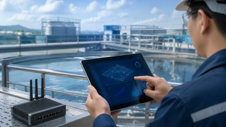
Tri State Water Conference 2025
Tri State Water Conference 2025
The Tri State Water Conference 2025 stands as a critical milestone for engineers, municipal planners, and industrial operators focused on the evolving landscape of water resource management. As water scarcity and aging infrastructure become more pressing concerns, the adoption of advanced instrumentation becomes a necessity rather than an option. For professionals attending the Tri State Water Conference 2025, understanding the technical nuances of level measurement is essential for optimizing treatment processes, ensuring regulatory compliance, and reducing operational overhead.
Level measurement in the water and wastewater industry is not a one-size-fits-all discipline. It requires a deep understanding of fluid dynamics, environmental variables, and the physical principles that govern different sensing technologies. This guide provides a technical foundation for selecting and implementing level measurement solutions, aligning with the engineering standards discussed at major industry gatherings like the Tri State Water Conference 2025.
The Role of Level Measurement in Modern Water Infrastructure
In both municipal and industrial water cycles, level measurement serves as the "eyes" of the automation system. Accurate data is required for:
1. Inventory Management: Monitoring chemical tanks for dosing (e.g., sodium hypochlorite or alum).
2. Process Control: Maintaining optimal levels in aeration tanks, clarifiers, and filtration beds.
3. Safety and Compliance: Preventing overflows in lift stations and monitoring discharge levels in compliance with environmental permits.
4. Resource Optimization: Managing reservoir levels and groundwater extraction to ensure sustainable supply.
As highlighted in the Main Page of industrial instrumentation resources, the transition toward "Smart Water" systems relies heavily on the reliability of these primary sensors.
Core Measurement Principles for Water Applications
Before selecting a device, it is imperative to understand the physics behind the measurement. For the water industry, four primary technologies dominate the market: Radar, Ultrasonic, Hydrostatic, and Magnetic.
1. Radar Level Measurement (Non-Contact)
Radar level meters operate on the Time-of-Flight (ToF) principle. The sensor emits a high-frequency electromagnetic pulse (typically in the 26 GHz or 80 GHz range). This pulse travels at the speed of light, reflects off the surface of the liquid, and returns to the receiver. The distance ($D$) is calculated as $D = (c \times t) / 2$, where $c$ is the speed of light and $t$ is the measured time.
* Advantages: Radar is unaffected by air temperature, pressure, or the presence of vapors. 80 GHz radar, in particular, offers a narrow beam angle, allowing for accurate measurement in narrow tanks or basins with internal obstructions.
* Application: Ideal for chemical storage tanks and turbulent wastewater pits.
2. Ultrasonic Level Measurement (Non-Contact)
Similar to radar, ultrasonic sensors use the ToF principle but utilize sound waves instead of electromagnetic pulses. The sensor emits an ultrasonic pulse (usually between 20 kHz and 200 kHz).
* Physics Limitation: The speed of sound is highly dependent on air temperature ($v \approx 331.5 + 0.6T$, where $T$ is in Celsius). Therefore, integrated temperature compensation is mandatory for accuracy.
* Application: Widely used in open channel flow measurement and standard water tank monitoring where conditions are stable.
3. Hydrostatic Level Measurement (Contact)
This method relies on the relationship between liquid height and pressure: $P = \rho \times g \times h$, where $P$ is pressure, $\rho$ is the density of the liquid, $g$ is gravity, and $h$ is the height of the liquid column. A submersible pressure transmitter measures the head pressure of the liquid above it.
* Considerations: The sensor must be compensated for atmospheric pressure, usually via a vented cable. It is highly effective for deep wells and reservoirs where non-contact sensors might struggle with range or mounting.
4. Magnetic Level Gauges
Used primarily for visual indication with an optional electronic output, these devices use a float containing a magnet that moves with the liquid level inside a bypass chamber. The magnet flips colored flags or actuates a reed chain transmitter.
* Application: Best suited for high-pressure boiler water or closed chemical vessels where a physical bypass is preferred for safety.
Selection Criteria and Technical Comparison
When evaluating technologies at the Tri State Water Conference 2025, engineers should use a structured selection matrix. The choice depends on the media characteristics, the physical environment, and the required accuracy.
Technical Selection Table
| Feature | Radar (80 GHz) | Ultrasonic | Hydrostatic | Magnetic Gauge |
| :— | :— | :— | :— | :— |
| Measurement Range | Up to 120m (393 ft) | Up to 15m (49 ft) | Up to 200m (656 ft) | Up to 6m (20 ft) |
| Accuracy | ±1 mm to ±2 mm | ±0.25% of range | ±0.1% to ±0.5% | ±5 mm |
| Media Influence | Dielectric constant | Foam/Vapor/Wind | Density changes | Specific gravity |
| Contact Type | Non-contact | Non-contact | Contact (Submerged) | Contact (Bypass) |
| Maintenance | Very Low | Low | Moderate (Cleaning) | Moderate |
| Typical Cost | High | Low to Medium | Medium | Medium to High |
Installation Best Practices for Reliable Data
Even the most advanced sensor will fail if installed incorrectly. Engineering teams preparing for upgrades following the Tri State Water Conference 2025 should adhere to these installation guidelines:
1. Avoid the "Dead Zone"
Every non-contact sensor has a "dead zone" or "near-range blanking" area directly beneath the transducer where measurement is impossible. For an ultrasonic sensor, this might be 0.25m to 0.5m (10 to 20 inches). Ensure the sensor is mounted high enough that the maximum liquid level never enters this zone.
2. Beam Path Obstructions
For radar and ultrasonic sensors, the signal spreads as it travels (the beam angle). If the beam hits a ladder, a pipe, or the tank wall, it creates a "false echo."
* Solution: Use 80 GHz radar for narrow beam requirements (as small as 3°). If obstructions are unavoidable, use the software's "false echo suppression" or "masking" feature during commissioning.
3. Turbulence and Foam
Surface turbulence can scatter signal pulses, while heavy foam can absorb them entirely.
* Mitigation: In turbulent tanks, use a stilling well (a vertical pipe) to provide a calm surface for the sensor to measure. For foam, radar is generally more resilient than ultrasonic, but high-frequency radar may still see foam as a surface. In these cases, hydrostatic transmitters are often the most reliable choice as they measure from the bottom up.
4. Submersible Sensor Anchoring
Hydrostatic sensors in moving water (like a river or an agitated tank) should be housed in a protective pipe or anchored with a weight to prevent the sensor from moving, which would cause erratic pressure readings.
Addressing Common Risks and Limitations
In the context of the Tri State Water Conference 2025, much discussion centers on risk mitigation. In level measurement, risks typically manifest as data drift or total signal loss.
* Environmental Factors: In outdoor installations, ultrasonic sensors can be affected by wind blowing the sound wave or heavy rain creating noise. Radar is immune to these factors.
* Build-up and Scaling: In wastewater applications, grease and solids can build up on contact sensors. Hydrostatic diaphragms should be inspected periodically for "clogging." Non-contact sensors are preferred here, but even they can suffer if condensation or splash-back dries on the transducer face. Choosing a sensor with a PTFE or PFA wetted face can minimize adhesion.
* Power Supply Stability: Many industrial level meters are 2-wire loop-powered (4-20mA). Ensure the PLC or controller provides sufficient voltage (typically 12-36V DC) after accounting for the voltage drop across the entire loop length.
Frequently Asked Questions (FAQs)
Q: How does the dielectric constant affect radar measurement?
A: Radar relies on the reflection of electromagnetic waves. The strength of this reflection depends on the dielectric constant ($ε_r$) of the liquid. Water has a high $ε_r$ (~80), making it an excellent reflector. Hydrocarbons have low $ε_r$ values (~2), requiring more sensitive radar electronics.
Q: Can I use one level sensor for all my water treatment stages?
A: While radar is versatile, it may be overkill for a simple clear-water storage tank where an ultrasonic sensor is more cost-effective. Conversely, an ultrasonic sensor will fail in a pressurized chemical tank where gas layers change the speed of sound. A site-wide audit is recommended to match technology to the specific application.
Q: What is the benefit of 80 GHz radar over 26 GHz?
A: The higher frequency (80 GHz) allows for a much smaller antenna and a narrower beam. This results in better signal focus, allowing the sensor to ignore internal tank structures and provide a more accurate reading in confined spaces.
Q: How often should level meters be calibrated?
A: For most water applications, an annual verification is sufficient. However, for custody transfer or high-stakes environmental discharge, semi-annual calibration against a manual tape measure or a secondary reference is standard practice.
Conclusion
The Tri State Water Conference 2025 provides a platform for professionals to refine their approach to water management. As we have explored, the selection of level measurement technology requires a balance of physical principles, environmental awareness, and budgetary considerations. Whether implementing radar for its precision or hydrostatic sensors for their reliability in deep-well applications, the goal remains the same: high-quality data for better decision-making.
For those seeking to upgrade their infrastructure or integrate new technologies discussed at the Tri State Water Conference 2025, reviewing the comprehensive options available on the Main Page is a recommended next step. By applying these engineering principles, water professionals can ensure their systems are resilient, accurate, and ready for the challenges of 2025 and beyond.