Heat Flow Meter Apparatus
Heat Flow Meter Apparatus
In the realm of industrial thermal management and material science, the accurate determination of thermal conductivity is a cornerstone for process efficiency and safety. The heat flow meter apparatus (HFMA) stands as the primary instrument for measuring the steady-state heat transfer properties of low-conductivity materials, such as insulation, polymers, and composites. For engineers managing complex industrial systems—ranging from cryogenic storage to high-temperature chemical reactors—understanding the performance of these materials is essential for maintaining the integrity of the surrounding instrumentation, including advanced level measurement systems.
This guide provides a comprehensive technical overview of the heat flow meter apparatus, its operating principles, selection criteria, and its critical role in industrial applications where thermal stability and process control intersect.
Understanding the Measurement Principles of the Heat Flow Meter Apparatus
The heat flow meter apparatus operates on the principle of the steady-state method. Unlike transient methods that measure thermal diffusivity, the HFMA establishes a constant temperature gradient across a specimen to determine its thermal conductivity (λ).
1. Fourier’s Law of Heat Conduction
The fundamental physics governing the HFMA is Fourier’s Law, which states that the rate of heat transfer through a material is proportional to the negative gradient in the temperature and to the area at right angles to that gradient through which the heat flows. Mathematically, this is expressed as:
q = -λ ∇T
Where:
* q is the heat flux (W/m²).
* λ is the thermal conductivity (W/m·K).
* ∇T is the temperature gradient (K/m).
2. The Comparative Method
Unlike the Guarded Hot Plate (GHP) method, which is an absolute measurement technique, the heat flow meter apparatus is a comparative method. It uses one or more heat flux transducers (HFTs) calibrated against a standard reference material (SRM) of known thermal conductivity. The HFTs convert the thermal energy passing through the sample into an electrical voltage, which is then used to calculate the heat flow.
3. Steady-State Equilibrium
For a valid measurement, the apparatus must reach a state of thermal equilibrium. This occurs when the temperature of the hot and cold plates, as well as the heat flux readings, remain constant over a specified period. In industrial testing, reaching this state can take anywhere from 30 minutes to several hours, depending on the material's thickness and thermal mass.
Technical Standards: ASTM C518 and ISO 8301
To ensure consistency and global trade compliance, the operation of a heat flow meter apparatus is strictly governed by international standards. The two most prominent are:
* ASTM C518: Standard Test Method for Steady-State Thermal Transmission Properties by Means of the Heat Flow Meter Apparatus. This is the most widely used standard in North America for testing thermal insulation.
* ISO 8301: Thermal insulation — Determination of steady-state thermal resistance and related properties — Heat flow meter apparatus. This is the international counterpart, outlining similar requirements for equipment design and calibration.
These standards mandate that the apparatus be calibrated using materials certified by national metrology institutes, such as NIST (USA) or IRMM (Europe), ensuring that the data produced is traceable and accurate.
Key Components of an Industrial HFMA
A professional-grade heat flow meter apparatus consists of several critical sub-systems designed to minimize error and maximize repeatability:
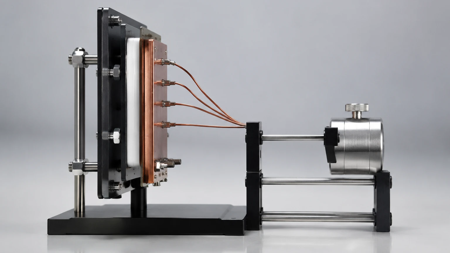
1. Hot and Cold Plates: These plates are typically made of high-conductivity aluminum and are equipped with precision heaters or Peltier cooling elements. They maintain a precise temperature differential across the sample.
2. Heat Flux Transducers (HFTs): These are thermopile-based sensors that generate a voltage proportional to the heat flow. High-end units often feature dual HFTs (one on each plate) to account for any internal heat loss and to improve measurement symmetry.
3. Thickness Sensors: Accurate thermal conductivity calculation requires precise knowledge of the sample thickness under the actual test conditions. Integrated digital encoders measure the distance between the plates to within 0.01 mm.
4. Temperature Control System: Utilizing PID (Proportional-Integral-Derivative) controllers and high-precision thermocouples or RTDs, the system maintains plate stability often within ±0.01°C.
Selection Criteria for Heat Flow Meter Apparatus
When selecting a heat flow meter apparatus for industrial or laboratory use, engineers must evaluate several technical specifications to ensure the equipment matches their material requirements.
| Parameter | Requirement/Specification | Industrial Significance |
| :— | :— | :— |
| Temperature Range | -20°C to 110°C (Standard) | Covers most building and process insulation needs. |
| Conductivity Range | 0.005 to 0.5 W/(m·K) | Essential for high-performance aerogels and foams. |
| Sample Size | 300 mm x 300 mm (Standard) | Standardized size for commercial insulation panels. |
| Thickness Range | 0 to 100 mm | Accommodates multi-layer or thick insulation samples. |
| Accuracy/Repeatability | ±1% to ±3% | Critical for R&D and quality control in manufacturing. |
| Compliance | ASTM C518 / ISO 8301 | Necessary for regulatory approval and certification. |
Installation and Operation Considerations
To achieve the precision required for B2B quality assurance, the installation and operation of the heat flow meter apparatus must follow strict protocols.
Sample Preparation
The sample must be representative of the bulk material. For rigid foams or boards, surfaces must be machined flat and parallel to within 0.25 mm. Any air gaps between the sample and the plates introduce thermal contact resistance, which can significantly underestimate the material's thermal conductivity.
Environmental Control
While the apparatus is insulated, it should ideally be operated in a temperature-controlled laboratory. Rapid fluctuations in ambient temperature can affect the cooling efficiency of the plates and extend the time required to reach steady-state equilibrium.
Pressure and Compression
Many insulation materials are compressible. The HFMA should allow for testing at specific pressures or thicknesses to simulate real-world installation conditions, such as the weight of a tank jacket or the pressure within a vacuum insulation panel (VIP).
Limitations and Factors Affecting Accuracy
While the heat flow meter apparatus is highly efficient, it is not a "one-size-fits-all" solution. Engineers must be aware of its limitations:
* High-Conductivity Materials: The HFMA is not suitable for metals or dense ceramics (λ > 2.0 W/m·K). The heat flux generated by these materials is too high for standard HFTs to measure accurately without significant edge heat loss.
* Non-Homogeneous Samples: If a sample has large internal voids or metallic inclusions, the heat flow will not be uniform. This violates the assumption of one-dimensional heat flow, leading to erroneous data.
* Moisture Content: Thermal conductivity is highly sensitive to moisture. Samples should be dried to a constant mass before testing, or the moisture content must be strictly controlled and reported.
The Relationship Between Thermal Insulation and Level Measurement
In the context of industrial process automation, the data derived from a heat flow meter apparatus is vital for the correct implementation of level measurement instruments. Welk, a professional manufacturer of industrial level measurement instruments, provides solutions like radar, ultrasonic, and hydrostatic level transmitters that often operate in environments where thermal management is critical.
Impact on Level Sensor Performance
1. Temperature Gradients in Tanks: If the insulation of a storage tank (verified by HFMA testing) is insufficient, large temperature gradients can form in the headspace. For ultrasonic level sensors, this changes the speed of sound, necessitating complex compensation. For radar level meters, extreme heat can affect the dielectric properties of the vapor space.
2. Electronic Protection: Level transmitters are often mounted on top of vessels containing hot or cold liquids. Understanding the heat flow through the tank walls and insulation allows engineers to specify the correct cooling extensions or heat shields to protect the sensor's electronics from thermal damage.
3. Density Compensation: In hydrostatic level measurement, the liquid density is a function of temperature. Accurate thermal characterization of the vessel's insulation helps in predicting the temperature profile of the liquid, ensuring more accurate level-to-volume conversions.
For a comprehensive review of instrumentation options and application support across these industrial scenarios, please visit our Main Page.
Frequently Asked Questions (FAQs)
Q: How often should a heat flow meter apparatus be calibrated?
A: Most standards recommend calibration at least once a year, or whenever the equipment is moved or repaired. However, many industrial labs perform a "check measurement" with a known sample weekly to ensure stability.
Q: Can the HFMA measure the thermal conductivity of liquids?
A: Standard HFMAs are designed for solids. Measuring liquids requires specialized cells to prevent convection, which would otherwise bypass the conductive heat transfer and lead to incorrect readings.
Q: What is the difference between thermal conductivity and thermal resistance?
A: Thermal conductivity (λ) is an intrinsic property of the material. Thermal resistance (R-value) depends on both the conductivity and the thickness of the material (R = d / λ). The HFMA measures both simultaneously.
Conclusion
The heat flow meter apparatus is an indispensable tool for the modern industrial landscape, providing the empirical data necessary to optimize thermal insulation and process efficiency. By adhering to standards like ASTM C518 and understanding the nuances of steady-state heat transfer, manufacturers can ensure their products meet the rigorous demands of the market. Furthermore, integrating this thermal data with high-quality process instrumentation, such as the radar and ultrasonic sensors provided by Welk, ensures that industrial operations remain safe, accurate, and cost-effective. For more information on integrating level measurement with your thermal management strategy, visit our Main Page.