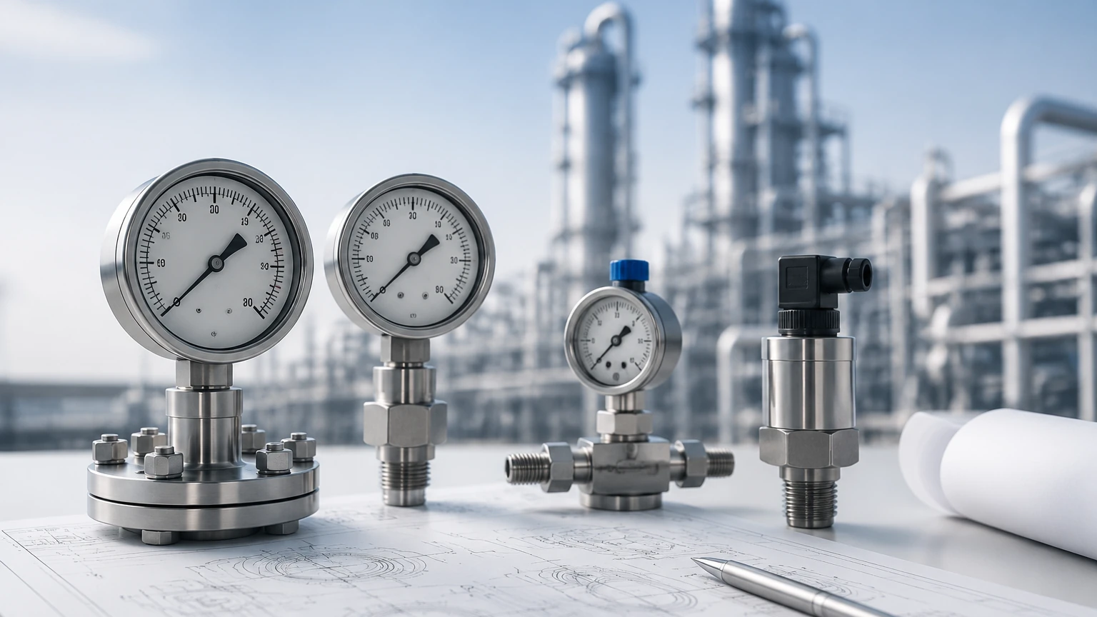
Pressure Measurement Instrumentation
Pressure Measurement Instrumentation
In the landscape of industrial automation and process control, pressure measurement instrumentation serves as a foundational technology. Whether monitoring the force within a steam boiler, ensuring the integrity of a chemical pipeline, or calculating the volume of liquid in a storage tank via hydrostatic head, accurate pressure data is critical for safety and efficiency. This guide explores the principles, types, and selection criteria for pressure instrumentation, specifically focusing on its application in industrial environments.
Fundamental Principles of Pressure Measurement
Before selecting a specific instrument, it is essential to understand the reference points used in pressure measurement. Pressure is defined as force per unit area, but in industrial applications, the "zero" reference point determines the type of measurement required.
1. Gauge Pressure (psig / bar g)
Gauge pressure is the most common type of measurement. It uses the current atmospheric pressure as its reference point. Therefore, a gauge pressure reading of zero indicates that the internal pressure is equal to the surrounding atmospheric pressure. This is typically used for vessel monitoring and piping systems where the structural integrity depends on the difference between internal and external forces.
2. Absolute Pressure (psia / bar a)
Absolute pressure is measured relative to a perfect vacuum (zero pressure). This measurement is necessary in applications where atmospheric pressure fluctuations—caused by weather changes or altitude—would introduce unacceptable errors. Common applications include vacuum distillation and high-precision atmospheric monitoring.
3. Differential Pressure (psid / bar d)
Differential pressure (DP) is the difference in pressure between two distinct points in a system. This principle is widely used in flow measurement (across an orifice plate) and filter monitoring. In the context of level measurement, DP transmitters are essential for pressurized tanks where the overhead gas pressure must be subtracted from the total bottom pressure to determine the liquid level.
The Relationship Between Pressure and Level
For many process engineers, pressure measurement instrumentation is the primary method for determining liquid level. This is known as the hydrostatic principle. The pressure exerted by a liquid column at rest is directly proportional to its height and the density of the fluid. The formula used is:
P = ρ × g × h
* P = Hydrostatic pressure (Pa or bar)
* ρ (rho) = Density of the liquid (kg/m³)
* g = Gravitational acceleration (approximately 9.81 m/s²)
* h = Height of the liquid column (m)
By measuring the pressure at the base of a tank, a transmitter can provide a continuous level reading. This method is highly reliable for liquids with constant density, such as water in municipal treatment plants or fuel in storage depots. For more complex level challenges, engineers often consult the Main Page of specialized manufacturers to compare hydrostatic transmitters against radar or ultrasonic alternatives.
Types of Pressure Measurement Sensors
Modern pressure measurement instrumentation utilizes several sensing technologies to convert mechanical force into an electrical signal.
* Piezoresistive Strain Gauges: These sensors utilize a diaphragm with integrated resistors. When pressure deforms the diaphragm, the electrical resistance changes. They are robust, cost-effective, and suitable for a wide range of industrial applications.
* Capacitive Sensors: A capacitive sensor measures the change in electrical capacitance between a sensing diaphragm and a fixed plate. These are known for high accuracy and excellent stability over time, making them ideal for low-pressure and differential pressure measurements.
* Ceramic Thick-Film Sensors: These are highly resistant to corrosion and abrasion. The ceramic material acts as both the diaphragm and the support structure, providing high chemical compatibility without the need for expensive exotic alloys.
Selection Criteria for Industrial Applications
Choosing the right pressure measurement instrumentation requires a detailed analysis of the process conditions. The following table provides a high-level comparison of selection factors:
| Criteria | Consideration | Impact on Instrument Choice |
| :— | :— | :— |
| Pressure Range | Minimum and maximum operating pressures. | Determines the sensor's "Full Scale" and overpressure limit. |
| Media Compatibility | Chemical properties of the fluid. | Dictates the material of the wetted parts (316L SS, Hastelloy, Tantalum). |
| Temperature | Process and ambient temperature ranges. | May require cooling fins, capillary tubes, or remote seals. |
| Accuracy | Required precision for the process. | Higher accuracy (e.g., 0.075% vs 0.5%) increases cost. |
| Output Signal | Integration with control systems. | 4-20mA, HART, RS485 (Modbus), or Profibus. |
| Process Connection | How the device attaches to the pipe/tank. | Threaded (NPT/G), Flanged (ANSI/DIN), or Hygienic (Tri-clamp). |
Installation Considerations and Best Practices
Even the most advanced pressure measurement instrumentation will fail to provide accurate data if installed incorrectly. Engineers should adhere to the following guidelines during the design and installation phase:
1. Mounting Position: For liquid applications, the transmitter should ideally be mounted below the tapping point to ensure that the impulse lines remain filled with liquid and air bubbles can escape back into the process. For gas applications, the instrument should be mounted above the tapping point to allow condensate to drain away.
2. Impulse Piping: The lines connecting the process to the sensor should be as short as possible to minimize lag and potential leak points. A slope of at least 1:12 is recommended to prevent gas or liquid entrapment.
3. Isolation and Manifolds: Always install a block-and-bleed valve or a multi-valve manifold. This allows for the safe removal, venting, and in-situ calibration of the instrument without shutting down the entire process line.
4. Environmental Protection: While most industrial transmitters are rated IP65 or higher, extreme environments may require sunshades to prevent thermal drift or heat tracing to prevent the process media from freezing in the impulse lines.
Limitations and Potential Risks
While pressure measurement instrumentation is versatile, it is not a "one-size-fits-all" solution. Understanding the limitations is key to avoiding measurement errors.
* Density Fluctuations: In hydrostatic level applications, if the temperature of the liquid changes significantly, its density will change. Since the pressure transmitter only measures weight (force), it cannot distinguish between a change in level and a change in density unless compensated by a secondary temperature sensor or a PLC algorithm.
* Viscous and Clogging Media: Standard pressure ports can become clogged by slurries, polymers, or fluids that solidify at ambient temperatures. In these cases, a flush diaphragm or a chemical seal (remote seal) must be used to isolate the sensor from the media.
* Mechanical Vibration: High-frequency vibration from pumps or compressors can cause mechanical fatigue in the sensor diaphragm or electronic failure. Utilizing remote mounting with capillary tubes can isolate the instrument from these vibrations.
* Overpressure Events: Sudden pressure spikes (water hammer) can permanently deform the sensing element. Selection should always account for the maximum possible surge pressure, not just the nominal operating pressure.
Frequently Asked Questions (FAQs)
Q: How often should pressure measurement instrumentation be calibrated?
A: Calibration frequency depends on the criticality of the process and the stability of the instrument. In regulated industries (like pharmaceuticals), annual or semi-annual calibration is standard. For general industrial use, a check every 24 months is often sufficient, provided the instrument shows no signs of drift.
Q: What is the difference between a pressure transmitter and a pressure transducer?
A: While the terms are often used interchangeably, a transducer typically provides a raw voltage output (e.g., 0-10V), whereas a transmitter converts the signal into a standardized current loop (e.g., 4-20mA) capable of long-distance transmission with high noise immunity.
Q: Can I use a gauge pressure transmitter for vacuum measurement?
A: Some gauge transmitters are designed to handle "compound" ranges (e.g., -1 bar to +10 bar). However, for deep vacuum applications, a dedicated absolute pressure transmitter is required to achieve the necessary accuracy.
Q: Why is HART protocol important in pressure instrumentation?
A: HART (Highway Addressable Remote Transducer) allows for digital communication over the standard 4-20mA analog wiring. It enables remote configuration, diagnostics, and the transmission of secondary variables (like sensor temperature) without additional cabling.
Conclusion
Effective process control begins with reliable data. Pressure measurement instrumentation provides the essential metrics needed to maintain safety, optimize throughput, and ensure product quality. By understanding the underlying physics of gauge, absolute, and differential pressure, and by carefully matching instrument specifications to the rigors of the industrial environment, engineers can implement robust measurement solutions. For those integrating these sensors into broader level control systems, reviewing technical specifications on the Main Page can provide further clarity on how pressure technology complements other sensing modalities like radar or ultrasonic measurement.