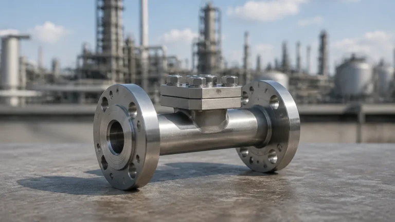
Pressure to Current Transducer
Pressure to Current Transducer
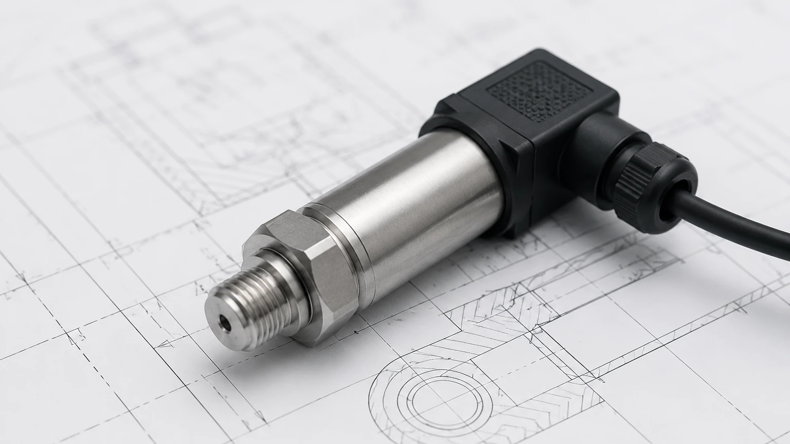
In the landscape of industrial automation and process control, the pressure to current transducer serves as a fundamental bridge between physical mechanical forces and electronic control systems. Often referred to interchangeably as a pressure transmitter, this device is engineered to sense pressure from gases or liquids and convert that physical value into a standardized electrical current signal, most commonly 4-20 mA. This conversion is essential for transmitting data over long distances without signal degradation, making it a cornerstone technology for industries ranging from water treatment to chemical processing.
For engineers and technicians, understanding the nuances of how a pressure to current transducer operates—and how to select the right one for specific applications like hydrostatic level measurement—is critical for ensuring system reliability and accuracy. As a professional manufacturer, Welk provides a range of these instruments designed to meet the rigorous demands of industrial environments.
Measurement Principles of Pressure to Current Transducers
The operation of a pressure to current transducer relies on two primary stages: the sensing element (transducer) and the signal conditioning electronics (transmitter).
1. The Sensing Element
When pressure is applied to the transducer, it acts upon a diaphragm. The physical displacement or stress on this diaphragm is captured by a sensor. The three most common sensing technologies include:
* Piezoresistive Strain Gauges: These utilize the change in electrical resistance of a material (usually silicon or metal foil) when it is stretched or compressed. This is the most common technology for general industrial applications due to its high sensitivity and stability.
* Capacitive Sensors: These measure the change in electrical capacitance between a sensing diaphragm and a fixed reference plate. As pressure moves the diaphragm, the distance between the plates changes, altering the capacitance. These are known for high accuracy and the ability to measure very low pressures.
* Ceramic Thick-Film Sensors: These are highly resistant to corrosive media. The pressure causes a slight deformation in a ceramic disc, which is measured by a bridge circuit printed on the back of the disc.
2. Signal Conversion (The 4-20 mA Loop)
Once the physical pressure is converted into a small millivolt (mV) signal by the sensor, the internal electronics of the transducer amplify and linearize this signal. In a 4-20 mA system, 4 mA represents the lower end of the pressure range (zero), and 20 mA represents the maximum rated pressure (span).
The 4-20 mA standard is preferred in B2B industrial settings for several reasons:
* Noise Immunity: Current signals are much less susceptible to electromagnetic interference (EMI) than voltage signals.
* Long-Distance Transmission: Unlike voltage, which drops over long wire runs, current remains constant throughout the loop regardless of wire resistance.
* Wire Break Detection: Because the "zero" signal is 4 mA rather than 0 mA, a system can immediately detect a broken wire or sensor failure if the current drops to zero.
Applications in Hydrostatic Level Measurement
One of the most frequent applications for a pressure to current transducer is determining the level of liquid in a tank or vessel, a method known as hydrostatic level measurement. This principle is based on the fact that the pressure at the bottom of a liquid column is directly proportional to the height of that liquid.
The mathematical relationship is defined as:
P = ρ × g × h
(Where P is pressure, ρ is the density of the liquid, g is the gravitational constant, and h is the height of the liquid).
By installing a pressure to current transducer at the bottom of a tank, or using a submersible version lowered into a well, the device measures the pressure exerted by the liquid. The electronics then output a 4-20 mA signal that a PLC (Programmable Logic Controller) or display meter interprets as a level measurement in meters or feet. This method is highly effective for water treatment, oil storage, and chemical vats where the density of the fluid remains relatively constant.
Technical Selection Criteria
Choosing the correct pressure to current transducer requires a detailed evaluation of the process environment. The following table provides a comparison of key factors to consider during the procurement phase.
| Feature | Piezoresistive (Silicon) | Ceramic Cell | Capacitive |
| :— | :— | :— | :— |
| Typical Accuracy | 0.25% to 0.5% FS | 0.5% to 1.0% FS | 0.075% to 0.1% FS |
| Media Compatibility | Clean liquids, non-corrosive gases | Corrosive chemicals, slurries | High-precision industrial fluids |
| Overpressure Limit | Moderate (2x to 3x) | High (up to 10x) | Very High |
| Cost | Economical | Mid-range | Premium |
| Best Use Case | General automation, HVAC | Chemical processing, wastewater | Oil & Gas, custody transfer |
Beyond the sensor type, engineers must confirm:
* Pressure Range: The maximum expected pressure should typically fall within 50-75% of the transducer's rated range to prevent damage from surges.
* Output Signal: While 4-20 mA is standard, some systems may require digital protocols like HART, Modbus, or RS485.
* Process Connection: Threaded (NPT/G), flanged, or submersible mounting options must match the existing infrastructure.
Installation Considerations and Best Practices
Proper installation is vital for the longevity and accuracy of a pressure to current transducer. Failure to follow engineering best practices often leads to signal drift or premature sensor failure.
1. Venting and Atmospheric Pressure
For gauge pressure measurements (pressure relative to the atmosphere), the transducer must have a way to "breathe." In submersible level sensors, this is achieved through a small vent tube integrated into the signal cable. It is essential to ensure this tube is not kinked, blocked, or exposed to moisture, as this would cause errors in the level reading as barometric pressure changes.
2. Mounting Location
The transducer should be mounted in a location where it is protected from extreme vibration and mechanical shock. In liquid applications, the sensor should ideally be placed where the fluid is relatively still. If installed in a pipe, it should be placed on the side or bottom to ensure the sensing diaphragm remains wetted and to avoid air pockets.
3. Wiring and Shielding
To maintain the integrity of the 4-20 mA signal, use twisted-pair shielded cabling. The shield should be grounded at only one end (usually the controller end) to prevent ground loops, which can introduce noise into the measurement.
Limitations and Common Challenges
While pressure to current transducers are robust, they are not without limitations:
* Temperature Sensitivity: All transducers experience some degree of thermal drift. High-quality units include internal temperature compensation, but extreme process temperatures may require the use of siphons or cooling elements to protect the sensor electronics.
* Media Build-up: In applications involving wastewater or slurries, material can accumulate on the diaphragm (clogging). In these cases, a flush-diaphragm design is preferred over a recessed port design.
* Specific Gravity Changes: Since hydrostatic level measurement depends on liquid density, any significant change in the temperature or composition of the liquid will change its density, leading to an inaccurate level reading unless the controller is recalibrated.
For those seeking comprehensive technical data or specific product models for industrial automation, you can Review product options and application support on the Welk Main Page to find solutions tailored to these challenges.
Frequently Asked Questions (FAQs)
Q: What is the difference between a pressure transducer and a pressure transmitter?
A: Historically, a "transducer" referred to a device with a voltage output (like 0-5V or 0-10V), while a "transmitter" referred to a device with a current output (4-20 mA). Today, the terms are often used interchangeably, though "pressure to current transducer" specifically denotes the 4-20 mA output functionality.
Q: How often should a pressure to current transducer be calibrated?
A: For most industrial applications, an annual calibration check is recommended. However, in critical chemical processes or custody transfer applications, semi-annual or quarterly calibration may be required to maintain regulatory compliance and accuracy.
Q: Can a pressure transducer measure vacuum?
A: Yes, specific "vacuum" or "compound" transducers are designed to measure pressures below atmospheric levels. A compound transducer can measure both vacuum and positive pressure in a single device.
Q: What happens if the polarity of the 4-20 mA loop is reversed?
A: Most modern industrial transducers, including those from Welk, feature reverse polarity protection. If the wires are swapped, the device simply will not power up, but it will not be damaged.
Conclusion
The pressure to current transducer is an indispensable tool in the modern industrial toolkit. By converting physical pressure into a reliable 4-20 mA signal, these devices enable precise monitoring and control of complex systems. Whether used for simple pressure monitoring in a hydraulic line or complex level measurement in a chemical reactor, selecting the right technology—be it piezoresistive, ceramic, or capacitive—is the first step toward operational excellence. By adhering to strict installation guidelines and understanding the limitations of the technology, engineers can ensure long-term accuracy and safety in their facilities.