Pressure Transducer Measurement
Pressure Transducer Measurement
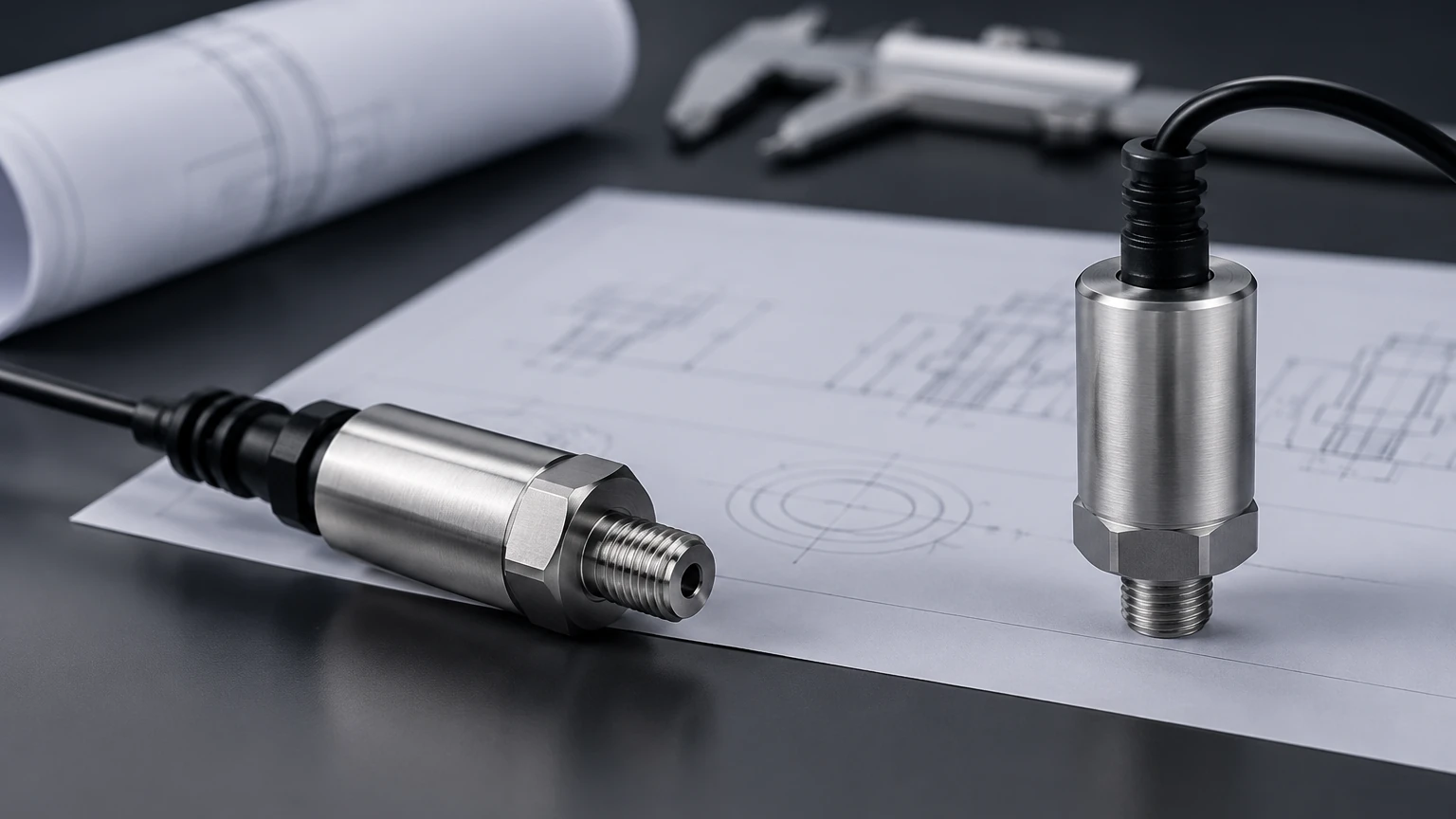
In the landscape of industrial automation and process control, pressure transducer measurement serves as a cornerstone for determining liquid levels in tanks, reservoirs, and deep wells. This method, primarily based on the principles of hydrostatics, offers a reliable and cost-effective alternative to non-contact technologies like radar or ultrasonic sensors in many applications. By converting the physical force of a liquid column into an electrical signal, pressure transducers provide real-time data essential for inventory management, pump control, and safety monitoring.
For engineers and facility managers, understanding the nuances of pressure transducer measurement is vital for selecting the right instrument. This guide explores the underlying physics, various transducer types, selection criteria, and practical installation strategies to ensure long-term accuracy in demanding industrial environments.
Principles of Hydrostatic Level Measurement
The fundamental principle behind using a pressure transducer for level measurement is the hydrostatic law. This law states that the pressure at a specific point in a static fluid is directly proportional to the height of the fluid column above that point, provided the density of the fluid remains constant.
The Mathematical Foundation
The relationship is expressed by the formula:
P = ρ × g × h
Where:
* P is the hydrostatic pressure (measured in Pascals or bar).
* ρ (rho) is the density of the liquid (kg/m³).
* g is the acceleration due to gravity (approximately 9.81 m/s²).
* h is the height of the liquid column (meters).
In practical application, if the density of the liquid and the gravitational constant are known, the pressure transducer measurement can be easily converted into a level reading. For example, a water column of 10 meters (32.8 ft) exerts a pressure of approximately 1 bar (14.5 psi) at the base. Most modern transmitters perform this conversion internally, outputting a signal scaled directly to the desired units of depth or volume.
Atmospheric Pressure Compensation
It is critical to distinguish between gauge pressure and absolute pressure. In vented or open tanks, the surface of the liquid is subject to atmospheric pressure. To measure only the liquid level, the transducer must compensate for changes in barometric pressure. This is typically achieved using a "gauge" sensor, which features a vent tube in the cable that allows the sensor's internal reference to stay at atmospheric pressure, effectively canceling out the weight of the air above the liquid.
Types of Pressure Transducers for Level Sensing
Not all pressure transducers are designed the same. The choice of hardware depends largely on the mounting requirements and the nature of the process fluid.
1. Submersible Pressure Transmitters
These are specialized sensors designed to be lowered directly into the liquid. They are housed in IP68-rated waterproof enclosures, usually made of stainless steel. The cable includes a specialized vent tube to ensure accurate gauge pressure readings. Submersible units are ideal for deep wells, wastewater lift stations, and large reservoirs where top-mounting is the only feasible option.
2. Externally Mounted Transmitters
In many industrial tanks, the transducer is mounted to a threaded port or flange at the bottom or side of the vessel. These sensors measure the head pressure of the liquid above the mounting point. They are easier to maintain than submersible units because they do not require pulling the sensor out of the liquid for inspection.
3. Differential Pressure (DP) Transmitters
For pressurized vessels—such as those found in chemical processing or oil and gas—a standard gauge pressure sensor will fail because it cannot distinguish between the liquid's head pressure and the gas blanket pressure. DP transmitters measure the difference between the bottom of the tank (liquid + gas pressure) and the top of the tank (gas pressure only), yielding an accurate measurement of the liquid level alone.
Key Evaluation Criteria for Pressure Transducer Measurement
When evaluating a pressure transducer for a specific project, several technical factors must be confirmed to ensure the device is fit for purpose.
| Criteria | Description | Importance |
| :— | :— | :— |
| Accuracy | Usually expressed as a percentage of Full Scale (e.g., ±0.25% FS). | Higher accuracy is required for custody transfer or precise chemical dosing. |
| Material Compatibility | The diaphragm material (316L SS, Tantalum, Ceramic). | Must resist corrosion from the process fluid (e.g., acids, seawater). |
| Pressure Range | The maximum expected head pressure. | Selecting a range too high reduces resolution; too low risks overpressure damage. |
| Output Signal | 4-20mA, 0-10V, RS485 (Modbus), or HART. | Must be compatible with the local PLC or SCADA system. |
| Temperature Range | The operating temperature of the fluid and environment. | Extreme temperatures can cause signal drift or diaphragm fatigue. |
| Long-term Stability | The sensor's ability to maintain calibration over time. | Reduces the frequency of maintenance and re-calibration cycles. |
Selecting the right instrument involves balancing these technical requirements against the project budget. For high-performance industrial solutions, engineers often consult a Main Page of a specialized manufacturer to compare detailed specifications across different sensor families.
Industrial Application Selection Table
Different industries face unique challenges, from high-viscosity fluids to explosive atmospheres. The following table provides general recommendations for common scenarios.
| Application | Fluid Characteristics | Recommended Transducer Type | Key Consideration |
| :— | :— | :— | :— |
| Water Treatment | Clear water, low solids | Submersible (Stainless Steel) | Use a protective cage if turbulence is high. |
| Chemical Storage | Corrosive acids/bases | External Flanged (PTFE/Ceramic) | Ensure diaphragm and seal compatibility. |
| Wastewater | Sludge, debris, foam | Large Diaphragm Submersible | Non-clogging design is essential. |
| Fuel Tanks | Flammable hydrocarbons | Intrinsically Safe (Ex ia) | Must meet ATEX/IECEx safety standards. |
| Food & Beverage | High temp, hygienic | Tri-clamp Sanitary Transmitter | Must support CIP (Clean-in-Place) processes. |
Installation Best Practices and Considerations
Even the most accurate pressure transducer measurement can be compromised by poor installation. Adhering to engineering best practices ensures the longevity and reliability of the system.
Positioning and Mounting
* Avoid the Bottom: In tanks where sediment or silt may accumulate, do not rest a submersible sensor on the very bottom. Suspend it at least 10 cm to 20 cm (4 to 8 inches) above the floor to prevent the diaphragm from being buried or clogged.
* Stilling Wells: In applications with high turbulence or agitators, install the sensor inside a stilling well (a vertical pipe with small holes). This protects the sensor from physical damage and prevents "noise" in the signal caused by moving liquid.
* Secure the Cable: For submersible units, ensure the cable is properly supported using a strain-relief clamp. The weight of a long cable should not be supported solely by the sensor connection.
Environmental Protection
* Venting: The vent tube in the cable must remain open to the atmosphere but protected from moisture. Use a desiccant cartridge or a specialized vent box to prevent water vapor from entering the tube, which can lead to internal corrosion or measurement errors.
* Lightning Protection: In outdoor installations (e.g., reservoirs), specify sensors with built-in surge protection to prevent damage from atmospheric electrical discharges.
Limitations and Common Risks
While pressure transducer measurement is versatile, it is not a "one-size-fits-all" solution. Engineers must be aware of its inherent limitations.
1. Density Sensitivity: Since the measurement relies on liquid density, any change in the fluid's composition or temperature will affect the accuracy. If a tank switches from water to a saline solution without recalibrating the transmitter, the level reading will be incorrect.
2. Mechanical Wear: Diaphragms are thin and can be damaged by abrasive particles or high-pressure spikes (water hammer). In slurries, a flush-diaphragm design is preferred to prevent buildup.
3. Vessel Pressurization: As noted earlier, standard pressure transducers cannot be used in sealed, pressurized tanks without a differential pressure setup. Using a gauge sensor in a pressurized tank will result in a reading that reflects the gas pressure rather than the liquid level.
Frequently Asked Questions (FAQs)
Q: How often should a pressure transducer be calibrated?
A: For most industrial applications, an annual calibration check is sufficient. However, in critical processes or harsh environments, semi-annual checks may be necessary to account for potential sensor drift.
Q: Can I use a pressure transducer for solids or powders?
A: Generally, no. Pressure transducers rely on the fluid properties of liquids to exert equal pressure in all directions. Solids do not behave this way, and the "pressure" at the bottom of a grain silo, for example, does not correlate linearly with height due to friction and bridging.
Q: What is the maximum depth a submersible sensor can measure?
A: This depends on the sensor's design. Standard industrial models can measure up to 200 meters (approx. 650 ft), while specialized deep-well sensors can go much deeper. Always match the sensor's rated range to the maximum possible depth of the application.
Q: Does foam on the surface affect the measurement?
A: One of the major advantages of pressure transducer measurement over ultrasonic or radar methods is that it is unaffected by surface foam. The sensor measures the weight of the liquid, and foam has negligible mass, meaning it does not interfere with the hydrostatic reading.
Conclusion
Pressure transducer measurement remains a primary choice for liquid level monitoring due to its simplicity and robustness. By understanding the relationship between pressure and depth, and by carefully selecting materials and mounting styles, process engineers can implement a solution that provides years of accurate data. For those seeking specific product configurations or technical support for complex applications, visiting the Main Page of an established manufacturer like Welk is the recommended next step to ensure all application-specific variables are addressed.