Pressure Transfucer
Pressure Transfucer
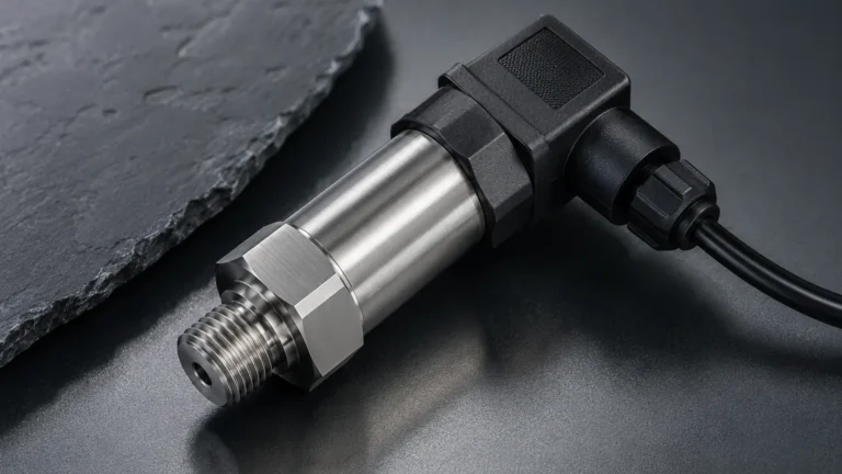
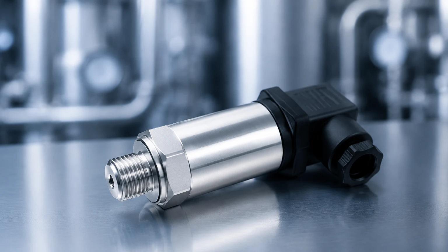
In the landscape of industrial automation and process control, the accurate measurement of force and liquid height is fundamental to operational safety and efficiency. A pressure transfucer—a term frequently encountered in procurement and technical searches as a variant of the pressure transducer—serves as the primary sensing element that converts mechanical pressure into a measurable electrical signal. Whether used for monitoring pipeline pressure or determining the depth of a liquid in a storage tank, understanding the mechanics, selection criteria, and installation requirements of these devices is essential for engineering professionals.
At Welk, we specialize in high-precision level measurement instruments, where the pressure transfucer often functions as the core component of hydrostatic level transmitters. This guide provides a comprehensive technical overview of these instruments, their principles of operation, and practical advice for selecting the right technology for industrial applications.
Measurement Principles of Pressure Transducers
To select the appropriate instrument, one must first understand how a pressure transfucer translates physical force into data. Most industrial sensors rely on one of two primary physical principles: piezoresistive sensing or capacitive sensing.
Piezoresistive Sensing (Strain Gauge)
This is the most common technology used in industrial pressure measurement. The sensor consists of a diaphragm, typically made of stainless steel or ceramic, with strain gauges bonded to its surface or diffused into a silicon substrate. When pressure is applied, the diaphragm deforms slightly, causing a change in the electrical resistance of the strain gauges. This change is measured using a Wheatstone bridge circuit and converted into a standardized electrical output, such as 4-20mA or 0-10V.
Ceramic Capacitive Sensing
In a capacitive pressure transfucer, the sensing element consists of two conductive plates separated by a small gap, with one plate acting as a flexible diaphragm. As pressure moves the diaphragm, the capacitance between the plates changes. This technology is highly valued for its robustness and resistance to overpressure and aggressive chemical media, making it a preferred choice for harsh industrial environments.
Hydrostatic Level Measurement
In the context of level measurement, a pressure transfucer is used to measure the hydrostatic pressure exerted by a liquid column. According to the principle of hydrostatics, the pressure (P) at the bottom of a tank is directly proportional to the height (h) of the liquid and its density (ρ), expressed by the formula:
P = ρ × g × h
(where g is the acceleration due to gravity). By measuring this pressure, the instrument can accurately calculate the liquid level, provided the density remains constant.
Key Evaluation Criteria for Industrial Selection
Choosing the correct pressure transfucer requires a detailed analysis of the process conditions. Failure to match the sensor specifications to the environment can lead to premature failure or inaccurate data.
1. Pressure Type and Range
* Gauge Pressure: Measured relative to atmospheric pressure. These sensors require a vent tube in the cable to equalize internal and external atmospheric pressure.
* Absolute Pressure: Measured relative to a perfect vacuum. Used in applications where atmospheric pressure fluctuations would affect the reading.
* Differential Pressure: Measures the difference between two pressure points, often used for filter monitoring or flow measurement.
2. Media Compatibility
The wetted parts of the sensor must be chemically compatible with the process fluid. While 316L stainless steel is standard, highly corrosive fluids like hydrochloric acid or seawater may require specialized materials such as Tantalum, Hastelloy, or PTFE coatings.
3. Accuracy and Stability
Industrial applications typically require accuracy ranging from 0.1% to 0.5% of the full scale (FS). Long-term stability is also a critical factor; high-quality sensors should exhibit minimal "drift" over years of service to reduce the frequency of recalibration.
4. Output Signals
* Analog (4-20mA): The industry standard for long-distance transmission with high noise immunity.
* Digital (HART, RS485/Modbus): Allows for remote configuration and diagnostic feedback, which is essential for Industry 4.0 integration.
Practical Selection Table
The following table summarizes the typical configurations for various industrial scenarios:
| Application | Recommended Sensor Type | Wetted Material | Typical Output |
| :— | :— | :— | :— |
| Clean Water Storage | Piezoresistive (Submersible) | 316L Stainless Steel | 4-20mA |
| Chemical Processing | Ceramic Capacitive | PTFE or Hastelloy | HART / 4-20mA |
| Oil & Gas Pipelines | Piezoresistive (High Pressure) | 316L / 17-4 PH SS | RS485 Modbus |
| Food & Beverage | Flush Diaphragm | 316L (Electropolished) | 4-20mA |
| Wastewater Sump | Large Diaphragm (Clog-resistant) | 316L + PVC Cable | 4-20mA |
Installation Considerations and Best Practices
The performance of a pressure transfucer is heavily dependent on how it is installed. Even the most accurate sensor will provide poor data if environmental factors are ignored.
Mounting Orientation
For hydrostatic level sensors, the unit should be mounted in a location where the fluid is relatively calm. In tanks with high turbulence or agitators, a stilling well (a perforated pipe) should be used to protect the sensor from mechanical stress and fluctuations.
Electrical Connections and Venting
If using a gauge pressure sensor, ensure the atmospheric vent tube in the cable is not kinked or blocked. It is recommended to use a moisture-proof vent filter at the termination point to prevent condensation from entering the sensor housing, which could cause internal short circuits.
Pressure Spikes and Pulsation
In pipeline applications, rapid valve closures can cause "water hammer" effects, creating pressure spikes many times higher than the rated range. In these cases, a pressure snubber or syphon should be installed to dampen the energy before it reaches the diaphragm.
Temperature Management
Standard sensors are typically rated for process temperatures between -20°C and +80°C (-4°F to 176°F). For high-temperature steam or furnace applications, cooling elements or capillary tubes must be used to isolate the electronics from the heat source.
Limitations and Risks
While highly versatile, the pressure transfucer has specific limitations that engineers must manage:
1. Density Sensitivity: Since hydrostatic level measurement relies on liquid density, any significant change in temperature or concentration that alters the density will result in a level error. In such cases, a radar or ultrasonic level meter may be more appropriate.
2. Clogging: In fluids with high solid content or viscous materials (like sludge or heavy oil), standard small-orifice pressure ports can clog. Flush diaphragm designs are required for these applications.
3. Overpressure Damage: Exceeding the burst pressure of the diaphragm will cause permanent deformation or rupture. Always select a sensor with an overpressure rating at least 2x the maximum expected process pressure.
Frequently Asked Questions (FAQs)
Q: What is the difference between a pressure transfucer and a pressure transmitter?
A: Technically, a transducer converts pressure into a low-level voltage signal (like millivolts), while a transmitter conditions that signal into a standardized industrial output like 4-20mA. However, in modern B2B procurement, the terms are often used interchangeably.
Q: How often should a pressure transfucer be calibrated?
A: For most industrial applications, an annual calibration check is recommended. However, in critical safety systems or highly corrosive environments, semi-annual checks may be necessary to ensure continued accuracy.
Q: Can I use a pressure sensor to measure the volume of a tank?
A: Yes. If the tank has a uniform shape, the level measurement can be converted to volume by the PLC or the transmitter itself. For non-linear tanks (like horizontal cylindrical tanks), a strapping table or linearization function is required.
Q: Is it possible to repair a damaged diaphragm?
A: No. The diaphragm is a precision-engineered component. If it is dented, scratched, or ruptured, the entire sensing element or the complete unit must be replaced to ensure safety and accuracy.
Conclusion and Next Steps
Selecting the right pressure transfucer is a balance between technical requirements and budget constraints. By understanding the measurement principles—whether piezoresistive or capacitive—and accounting for the specific challenges of the media and environment, engineers can ensure long-term reliability in their automation systems.
Welk provides a wide array of industrial instruments designed for the most demanding applications in water treatment, chemical processing, and oil and gas. For detailed technical specifications, CAD drawings, or to request a customized quote for your specific project needs, please visit our Main Page to review product options and application support. Our engineering team is available to assist in selecting the optimal configuration for your pressure and level measurement challenges.