Pressure Transmitter Sensor
Pressure Transmitter Sensor
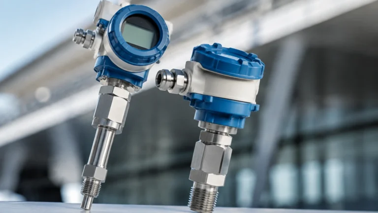
In the landscape of industrial automation and process control, the pressure transmitter sensor serves as a fundamental component for monitoring and managing system health. These devices are engineered to convert physical pressure—exerted by liquids, gases, or vapors—into a standardized electrical signal, typically 4-20mA or a digital protocol like RS485 Modbus. For engineers and procurement specialists, understanding the nuances of sensor technology is critical to ensuring long-term reliability and measurement accuracy in demanding environments such as water treatment, chemical processing, and oil and gas production.
Measurement Principles of Pressure Transmitter Sensors
Before selecting a pressure transmitter sensor, it is essential to understand the underlying physical principles that enable measurement. Most modern industrial sensors utilize one of three primary technologies to detect diaphragm displacement caused by pressure.
Piezoresistive Sensors
This is the most common technology used in industrial applications. A piezoresistive sensor consists of a diaphragm—usually made of stainless steel or ceramic—with strain gauges diffused into or bonded onto its surface. When pressure is applied, the diaphragm deforms, causing a change in the electrical resistance of the strain gauges. This change is proportional to the applied pressure. Piezoresistive sensors are favored for their high sensitivity, compact size, and cost-effectiveness.
Capacitive Sensors
Capacitive pressure transmitter sensors measure the change in electrical capacitance between a sensing diaphragm and a fixed reference electrode. As pressure moves the diaphragm, the distance between the plates changes, altering the capacitance. These sensors are known for their exceptional stability, high accuracy, and resistance to overpressure conditions. They are frequently used in low-pressure applications where precision is paramount.
Resonant Wire or Silicon Sensors
In these high-end sensors, a wire or a silicon resonator is kept in oscillation. Pressure applied to the diaphragm changes the tension of the wire or the stress on the silicon, which in turn shifts the resonant frequency. This frequency shift is measured and converted into a pressure reading. These sensors offer extreme precision and are often found in laboratory settings or critical custody-transfer applications.
The Relationship Between Pressure and Level Measurement
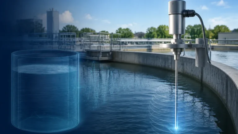
While pressure transmitter sensors are used to measure line pressure in pipes, they are also a cornerstone of hydrostatic level measurement. Welk specializes in utilizing these sensors to determine the depth of liquid in tanks and reservoirs based on the hydrostatic principle.
The relationship is defined by the formula:
P = ρ × g × h
Where:
* P is the hydrostatic pressure (measured in Pascals or bar).
* ρ (rho) is the density of the liquid (kg/m³).
* g is the acceleration due to gravity (approximately 9.81 m/s²).
* h is the height of the liquid column (meters).
By measuring the pressure at the bottom of a tank and knowing the density of the fluid, a pressure transmitter sensor can accurately calculate the liquid level. This method is highly effective for vented tanks. For pressurized vessels, a differential pressure transmitter is required to subtract the top-side gas pressure from the total pressure at the bottom.
Key Evaluation Criteria for Selection
Selecting the correct pressure transmitter sensor requires a detailed analysis of the application environment. Failure to account for chemical compatibility or thermal dynamics can lead to premature sensor failure or inaccurate data.
1. Pressure Type: Determine if you need absolute pressure (referenced to a vacuum), gauge pressure (referenced to atmospheric pressure), or differential pressure (the difference between two points).
2. Measurement Range: The sensor should be selected so that the operating pressure falls within 50% to 75% of the sensor’s full-scale range. This provides a buffer for pressure spikes while maintaining high resolution.
3. Media Compatibility: The wetted parts—the materials that come into direct contact with the fluid—must be chemically resistant. Common materials include 316L stainless steel for general water and oil, and Hastelloy or Tantalum for corrosive chemicals.
4. Output Signal: While 4-20mA is the industry standard due to its noise immunity over long distances, digital outputs like HART or Modbus are increasingly used for remote diagnostics and configuration.
5. Accuracy Class: Industrial sensors typically range from 0.1% to 0.5% of the full-scale span. Higher accuracy usually comes at a higher cost and may require more frequent calibration.
Technical Selection Table
The following table provides a general guide for matching sensor types with common industrial applications.
| Application Type | Recommended Sensor Technology | Typical Material | Key Benefit |
| :— | :— | :— | :— |
| Clean Water Storage | Submersible Piezoresistive | 316L Stainless Steel | Easy installation, low cost |
| Corrosive Chemical Tank | Flush Diaphragm Capacitive | PTFE or Hastelloy | Resists clogging and corrosion |
| High-Temperature Steam | Piezoresistive with Siphon | Stainless Steel | Thermal isolation of electronics |
| Viscous/Pulp Media | Flush Diaphragm | 316L / Ceramic | Prevents media buildup |
| Pressurized Fuel Tank | Differential Pressure | Stainless Steel / Monel | Accurate level despite head pressure |
Installation Considerations and Best Practices
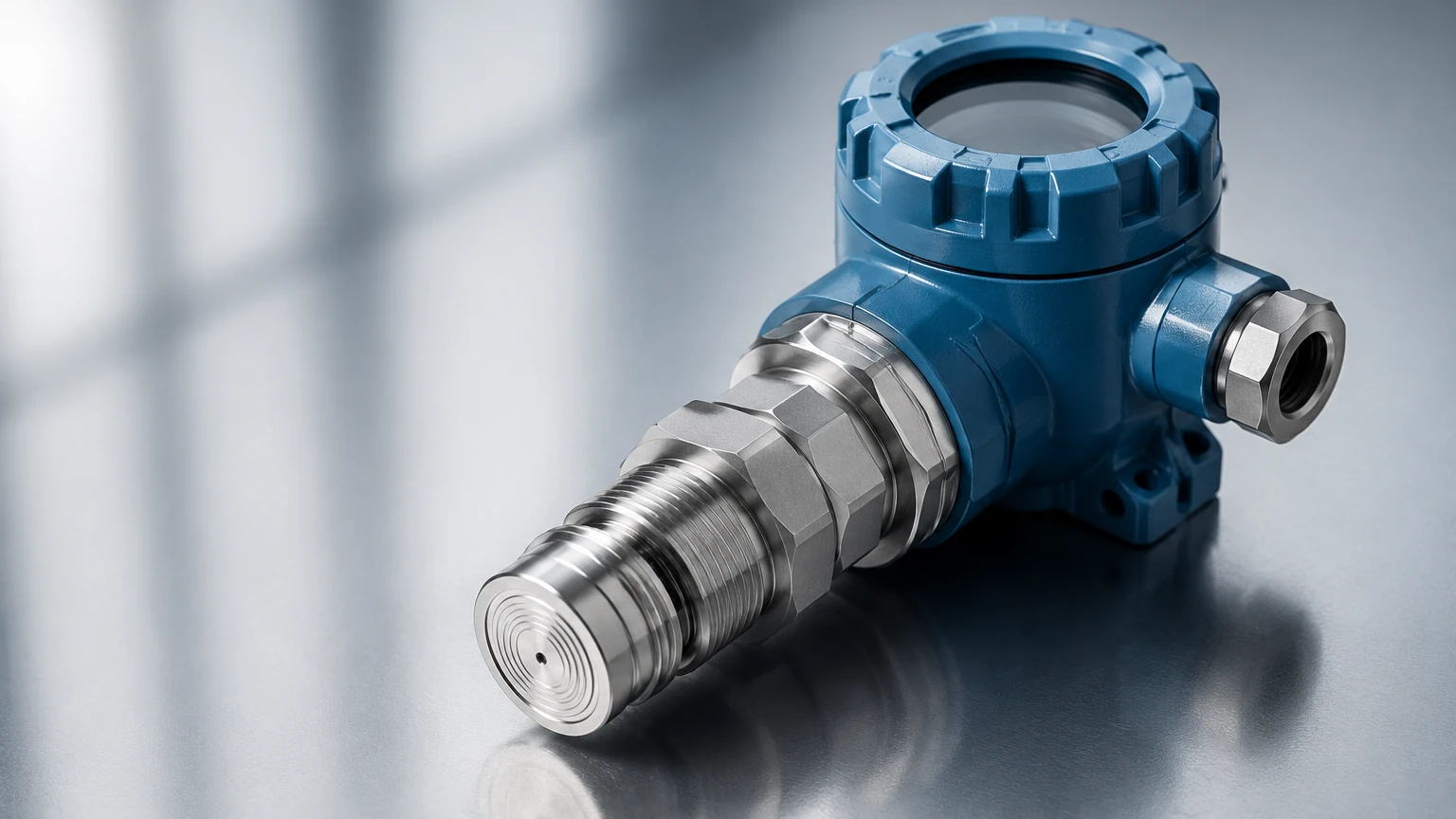
Proper installation is as critical as the selection of the pressure transmitter sensor itself. Even the most accurate sensor will provide faulty data if installed incorrectly.
Mounting Position
For liquid applications, the sensor should ideally be mounted below the tap point to prevent air bubbles from being trapped in the impulse lines. For gas applications, the sensor should be mounted above the tap point to allow condensate to drain back into the process line.
Impulse Lines and Venting
Impulse lines (the small-diameter pipes connecting the process to the sensor) should be kept as short as possible to minimize lag. For gauge pressure sensors, ensure the atmospheric vent—often a small tube inside the cable or a port on the housing—is kept clear of moisture and debris. If the vent is blocked, the sensor will experience "drift" as local barometric pressure changes.
Environmental Protection
In outdoor or wash-down environments, ensure the sensor has an appropriate Ingress Protection (IP) rating. IP67 is standard for most industrial use, while IP68 is required for continuous submersion. Using a conduit or a specialized cable gland can prevent water from traveling down the cable into the electronics housing.
Limitations and Common Risks
While pressure transmitter sensors are versatile, they are not without limitations. Engineers must be aware of the following risks to ensure system safety:
* Temperature Extremes: Standard sensors typically operate between -20°C and +80°C (-4°F to 176°F). For applications exceeding these limits, cooling elements or remote seals must be used to protect the sensing element.
* Pressure Spikes (Water Hammer): Rapid valve closures in piping systems can create pressure surges many times higher than the rated pressure. Utilizing a pressure snubber or choosing a sensor with high overpressure protection (e.g., 2x or 3x the range) is necessary in these scenarios.
* Zero Drift: Over time, all sensors experience a slight shift in their zero-point. This is often caused by mechanical stress or thermal cycling. Regular calibration (typically every 12 to 24 months) is required to maintain accuracy.
* Vacuum Conditions: Not all pressure sensors are designed to handle vacuum. Standard diaphragms may collapse or be damaged if exposed to negative pressure unless they are specifically rated for absolute or vacuum measurement.
Frequently Asked Questions (FAQs)
Q: What is the difference between a pressure transducer and a pressure transmitter?
A: While the terms are often used interchangeably, a pressure transducer typically outputs a raw voltage signal (e.g., 0-100mV), whereas a pressure transmitter includes conditioning electronics to output a standardized current signal (e.g., 4-20mA) that can be transmitted over long distances without signal loss.
Q: How do I handle measurement in a tank with high turbulence?
A: In turbulent tanks, a pressure transmitter sensor can be installed inside a stilling well (a vertical pipe with small holes). This dampens the surface movement and protects the sensor from mechanical impact, providing a much steadier level reading.
Q: Can a pressure sensor be used for density measurement?
A: Yes, by using two pressure sensors at a known vertical distance apart, the density of the fluid can be calculated based on the pressure difference between the two points. This is common in chemical blending and oil separation processes.
Q: Why is 4-20mA the preferred output for industrial sensors?
A: The 4-20mA loop is robust against electromagnetic interference (EMI) and allows the sensor to be powered by the same two wires used for signal transmission. Additionally, the "live zero" (4mA) allows the control system to detect a broken wire—if the current drops to 0mA, the system knows there is a fault.
Conclusion
The pressure transmitter sensor is a vital tool for modern industrial efficiency. By selecting the appropriate sensing technology, considering the chemical and thermal properties of the media, and following rigorous installation standards, facilities can achieve precise control over their processes. For a comprehensive overview of available sensing technologies and specific model data, engineers can visit the Main Page to review product options and application support. Whether monitoring water levels in a remote reservoir or managing high-pressure steam in a power plant, the right sensor provides the data necessary for safe and optimized operations.