Prosonic Fdu91
Prosonic Fdu91
In the landscape of industrial automation, precise level measurement is a cornerstone of process efficiency, safety, and inventory management. Among the various technologies available, ultrasonic sensors remain a preferred choice for non-contact measurement in water treatment, chemical processing, and bulk solids handling. The Prosonic FDU91 represents a specific class of ultrasonic transducers designed for continuous level measurement of fluids, pastes, and coarse bulk materials. This guide explores the engineering principles, technical specifications, and practical application considerations for the Prosonic FDU91 and similar ultrasonic technologies used in modern industrial environments.
Understanding Ultrasonic Level Measurement Principles
Before selecting a specific instrument like the Prosonic FDU91, it is essential to understand the physics of ultrasonic measurement. This technology is based on the "Time-of-Flight" (ToF) principle.
An ultrasonic transducer acts as both a transmitter and a receiver. It emits a series of high-frequency sound pulses—typically above the range of human hearing—which travel through the air or gas space in a vessel. When these waves encounter the surface of the medium (liquid or solid), they are reflected back toward the sensor. The instrument measures the time interval between the emission of the pulse and the reception of the echo.
Since the speed of sound in air is approximately 343 meters per second at 20°C, the distance ($D$) to the surface can be calculated using the formula:
$D = \frac{v \cdot t}{2}$
Where:
* $v$ is the velocity of sound in the medium.
* $t$ is the measured time-of-flight.
The result is divided by two because the pulse travels the distance twice (down and back). To ensure accuracy, the system must account for the distance from the sensor's reference point to the bottom of the tank (the calibration distance). By subtracting the measured distance from the total tank height, the controller determines the actual level of the material.
Temperature Compensation
A critical factor in ultrasonic measurement is that the speed of sound varies with the temperature of the gas through which it travels. An increase in temperature increases the speed of sound, which could lead to significant measurement errors if not corrected. The Prosonic FDU91 features an integrated temperature sensor within the transducer housing. This allows the connected transmitter to perform real-time compensation, ensuring that the level reading remains accurate despite fluctuating ambient or process temperatures.
Technical Overview of the Prosonic FDU91 Transducer
The Prosonic FDU91 is a robust transducer designed to interface with separate transmitter units, such as the Prosonic S FMU90 or FMU95. This modular approach allows the sensitive electronics of the transmitter to be mounted in a control room or a less harsh environment, while the transducer is exposed to the process conditions.
Key Specifications
* Measuring Range: Typically up to 10 meters (33 feet) in liquids and up to 5 meters (16 feet) in bulk solids. The actual range depends on the reflective properties of the surface and environmental conditions.
* Blocking Distance: Like all ultrasonic sensors, the FDU91 has a "dead zone" or blocking distance, usually around 0.3 meters (1 foot). Measurement is not possible within this zone, so the sensor must be mounted sufficiently high above the maximum expected level.
* Beam Angle: The sensor features a narrow beam angle (approximately 11° at -3dB). A narrower beam is advantageous in narrow tanks or vessels with internal obstructions, as it reduces the risk of false echoes from walls or pipes.
* Materials of Construction: The housing is typically constructed from PVDF (Polyvinylidene fluoride), providing excellent chemical resistance, with EPDM seals.
* Environmental Rating: Often rated IP68, making it suitable for outdoor use and areas prone to flooding or heavy moisture.
Application Engineering and Selection Criteria
Choosing the right level measurement technology requires a comparison of ultrasonic sensors against other common methods like radar, hydrostatic pressure, or magnetic gauges. Engineers must evaluate the chemical compatibility, physical state of the medium, and the geometry of the installation site.
Selection Table: Technology Comparison
| Feature | Ultrasonic (FDU91) | Radar (80 GHz) | Hydrostatic | Magnetic Level Gauge |
| :— | :— | :— | :— | :— |
| Measurement Type | Non-contact | Non-contact | Contact (Pressure) | Contact (Bypass) |
| Medium | Liquids & Solids | Liquids & Solids | Liquids only | Liquids only |
| Accuracy | High (0.2% range) | Very High (±1mm) | Moderate | High (Visual) |
| Vacuum Suitability| No | Yes | Yes | Yes |
| Foam Sensitivity | High (Signal loss) | Moderate | None | None |
| Cost | Moderate | High | Low to Moderate | Moderate to High |
For many standard water and wastewater applications, the ultrasonic method provided by instruments found on the Main Page offers the best balance between cost and performance. However, if the process involves high pressure, vacuum, or heavy foam, alternative technologies like guided wave radar or hydrostatic transmitters may be required.
Common Use Cases
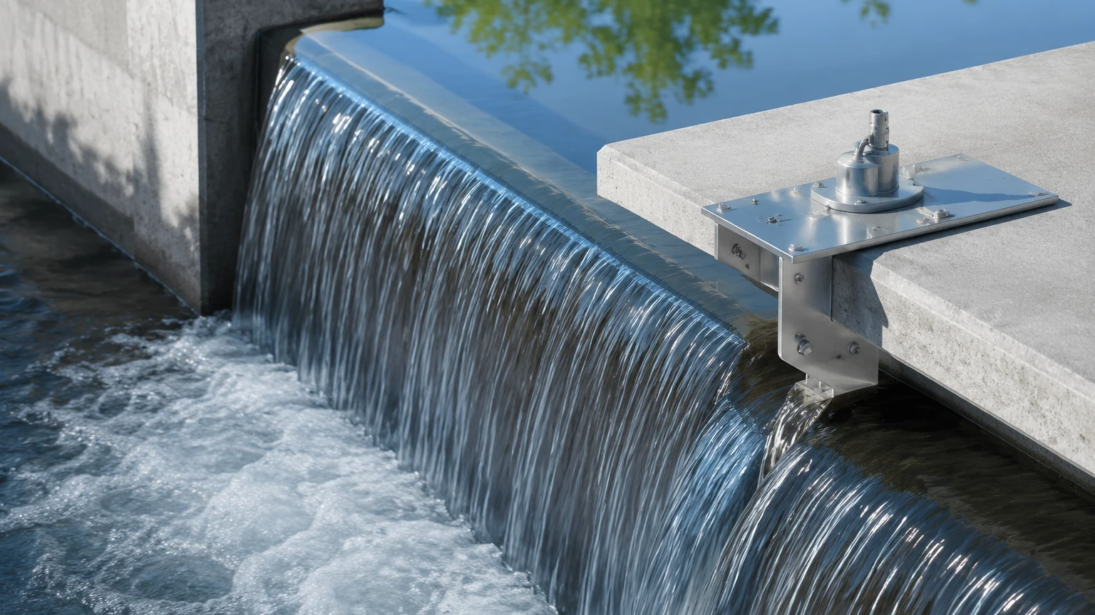
1. Open Channel Flow: Used in conjunction with flumes or weirs to measure flow rates in wastewater treatment plants.
2. Pump Stations: Monitoring wet wells to control pump start/stop cycles.
3. Storage Tanks: Tracking levels of water, diluted acids, or bases in chemical storage.
4. Bulk Solids: Measuring levels in small silos containing grain, plastic pellets, or crushed stone.
Installation Best Practices for Ultrasonic Sensors
The reliability of an ultrasonic level measurement system is heavily dependent on proper installation. Even the most advanced transducer, such as the Prosonic FDU91, will fail to provide accurate data if positioned incorrectly.
1. Orientation and Alignment
The transducer must be mounted perpendicular to the surface of the product. If the sensor is tilted, the ultrasonic pulse may reflect away from the transducer rather than back toward it, resulting in a "lost echo" error. In solids applications where the material forms a conical heap, an alignment device may be used to angle the sensor toward the slope for a better return signal.
2. Avoiding Obstructions
The ultrasonic beam spreads as it travels. Any internal tank structures—such as ladders, heating coils, or agitators—that enter the path of the beam will create false echoes. While modern transmitters offer "False Echo Suppression" (mapping out static reflections), it is best practice to mount the sensor at a distance from the tank wall (usually at least 1/6th of the tank diameter) and away from the inflow stream.
3. The Filling Curtain
Never install the sensor directly above the filling inlet. The falling stream of liquid or granules will scatter the ultrasonic signal and create significant noise, leading to erratic readings.
4. Weather Protection
When installed outdoors, the transducer should be protected from direct sunlight to prevent the integrated temperature sensor from overheating, which would cause an incorrect speed-of-sound calculation. A simple sunshade is often sufficient.
Limitations and Environmental Constraints
While versatile, ultrasonic technology has specific physical limitations that engineers must account for during the design phase.
Gas Composition and Vacuum
Ultrasonic waves require a medium (gas) to travel through. Therefore, these sensors cannot function in a vacuum. Furthermore, if the gas space above the liquid is not air but a heavy gas like Carbon Dioxide ($CO_2$) or a vapor like Ethanol, the speed of sound will differ significantly from air. If the gas composition is constant, the transmitter can be calibrated for it; however, if the composition fluctuates, the measurement will become inaccurate.
Foam and Turbulence
Surface foam is a common challenge. Light, airy foam tends to absorb ultrasonic pulses rather than reflecting them, leading to signal loss. In cases of heavy foam, a stilling well or a transition to radar or hydrostatic measurement is recommended. Similarly, extreme surface turbulence can scatter the signal, though software filtering in the transmitter can often mitigate this.
Dust and Condensation
Heavy dust in solids applications can attenuate the signal. While the FDU91 is designed to handle some dust, extremely high concentrations may require a sensor with a lower frequency and higher power. Condensation on the sensor face is another concern; many transducers feature a self-cleaning effect through the vibration of the sensor membrane, but in high-humidity environments, a PTFE-faced sensor may be preferable to prevent water droplets from clinging to the surface.
Integration with Control Systems and Transmitters
The Prosonic FDU91 is a component of a larger system. It must be connected to a transmitter that provides the power, signal processing, and communication interface.
The Role of the Transmitter
The transmitter (e.g., FMU90) performs the complex calculations required to turn time-of-flight into a level, volume, or flow reading. It typically provides:
* Output Signals: 4-20mA DC with HART protocol is standard. Fieldbus options like Profibus DP or Foundation Fieldbus are also common for integration into PLC or DCS systems.
* Relay Outputs: For high/low level alarms or pump control.
* Display: Local visualization of the level and configuration menus.
Wiring and Cable Management
The cable between the FDU91 and the transmitter is specialized to prevent interference. It should be run in grounded metal conduit if installed in areas with high electromagnetic interference (EMI). The maximum distance between the transducer and transmitter can often reach up to 300 meters, depending on the cable type and environment.
Maintenance and Troubleshooting Guide
Ultrasonic systems are generally low-maintenance because they have no moving parts. However, periodic checks ensure long-term reliability.
Routine Maintenance Tasks
* Visual Inspection: Check the transducer face for buildup of fats, oils, or crystallized chemicals. Clean gently with a soft cloth and water or a mild detergent if necessary.
* Verify Accuracy: Periodically compare the digital reading against a manual tape measure or a sight glass to ensure no drift has occurred.
* Check Seals: Inspect cable glands and housing seals to ensure no moisture is entering the connection compartment.
Troubleshooting Common Issues
* Reading stays at 100%: This often indicates the level has entered the blocking distance (dead zone). Check if the tank is overfilled or if the sensor is mounted too low.
* "Echo Lost" Error: This could be caused by heavy foam, extreme turbulence, or the sensor not being perpendicular to the surface. Check the surface conditions and sensor alignment.
* Erratic Readings: Often the result of false echoes from internal tank structures. Re-run the "False Echo Suppression" or "Tank Map" routine in the transmitter settings.
Frequently Asked Questions (FAQ)
Q: Can the Prosonic FDU91 be used in pressurized tanks?
A: Ultrasonic sensors are generally limited to near-atmospheric pressure. High pressure changes the density of the gas, which significantly alters the speed of sound and can damage the transducer membrane. For pressurized vessels, radar is usually the better choice.
Q: What is the difference between an ultrasonic transducer and an ultrasonic transmitter?
A: The transducer (like the FDU91) is the "head" that sends and receives the sound waves. The transmitter is the "brain" that processes the signal and provides the output. Some devices are "compact," meaning the transducer and transmitter are housed in a single unit.
Q: How does wind affect outdoor ultrasonic measurements?
A: Strong wind can "blow" the ultrasonic pulses away or create noise. However, in most standard applications like open channel flow, the effect is negligible unless the distance is very large or the wind is extreme.
Q: Can I use the FDU91 for measuring the level of acids?
A: Yes, provided the PVDF housing material is compatible with the specific acid and its concentration. Always consult a chemical compatibility chart before installation.
Conclusion
The Prosonic FDU91 remains a staple in industrial level measurement due to its reliability, non-contact nature, and effective temperature compensation. By understanding the underlying Time-of-Flight principle and adhering to strict installation guidelines, engineers can implement robust monitoring solutions for a wide variety of media. For those seeking comprehensive level measurement solutions, including radar and hydrostatic options, reviewing the extensive product range on the Main Page provides further insight into matching technology with specific process requirements. Proper selection and maintenance ensure that these instruments provide accurate data for years, contributing to the overall optimization of industrial operations.