Pump Station Control
Pump Station Control
Effective pump station control is the cornerstone of modern water management, wastewater treatment, and industrial fluid handling. At its core, a pump station control system manages the activation and deactivation of pumps to maintain specific fluid levels within a wet well, tank, or reservoir. By integrating precise level measurement instruments with automated logic, operators can prevent overflows, minimize energy consumption, and extend the mechanical lifespan of the pumping equipment.
In industrial environments, the reliability of these systems depends heavily on the accuracy of the primary sensing technology. Whether managing municipal sewage, industrial process water, or chemical runoff, the choice of level measurement technology determines the stability of the entire control loop. This guide explores the principles of level-based pump station control, the technologies available, and the engineering considerations necessary for a robust installation.
Principles of Level Measurement in Pump Stations
Before implementing a control strategy, it is essential to understand how the level is measured. Pump station control typically relies on one of four primary measurement principles: ultrasonic, radar, hydrostatic pressure, or point-level switching.
Ultrasonic Level Measurement
Ultrasonic sensors operate on the "Time of Flight" (ToF) principle. The sensor emits a high-frequency sound pulse that travels through the air, reflects off the liquid surface, and returns to the transducer. By measuring the time taken for the pulse to return and knowing the speed of sound, the instrument calculates the distance to the liquid.
* Advantages: Non-contact measurement, no moving parts, and relatively low cost.
* Limitations: Performance can be affected by heavy foam, extreme turbulence, or significant temperature fluctuations that alter the speed of sound.
Radar Level Measurement
Similar to ultrasonic sensors, radar level meters use ToF, but they emit electromagnetic microwave pulses instead of sound waves. These pulses travel at the speed of light and are largely unaffected by air temperature, pressure, or vapor layers.
* Advantages: High precision (often within ±2 mm), unaffected by steam or dust, and capable of penetrating foam in many instances.
* Limitations: Higher initial capital expenditure compared to ultrasonic or hydrostatic options.
Hydrostatic Level Measurement
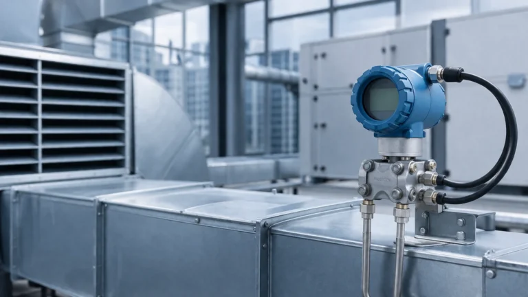
Hydrostatic transmitters are submersible pressure sensors placed at the bottom of the wet well. They measure the head pressure exerted by the liquid column above the sensor. Since pressure is directly proportional to the height of the liquid (based on the fluid's density), the transmitter provides a continuous level signal.
* Advantages: Simple installation, unaffected by surface foam or floating debris, and ideal for deep wells where mounting a top-down sensor is impractical.
* Limitations: The sensor is in constant contact with the fluid, making it susceptible to clogging in high-solids wastewater or corrosion in aggressive chemicals.
Point Level Switches
While continuous measurement is preferred for sophisticated control, point level switches (such as float switches or conductive probes) act as critical backups. They provide a simple "on/off" signal when the fluid reaches a specific height, often used for high-level alarms or redundant pump-stop commands.
Key Components of a Pump Station Control System
A functional pump station control architecture consists of more than just a sensor and a pump. To ensure long-term reliability, the following components must work in unison:
1. Primary Level Sensor: Provides the real-time data (4-20mA, Modbus, or HART signal) to the controller.
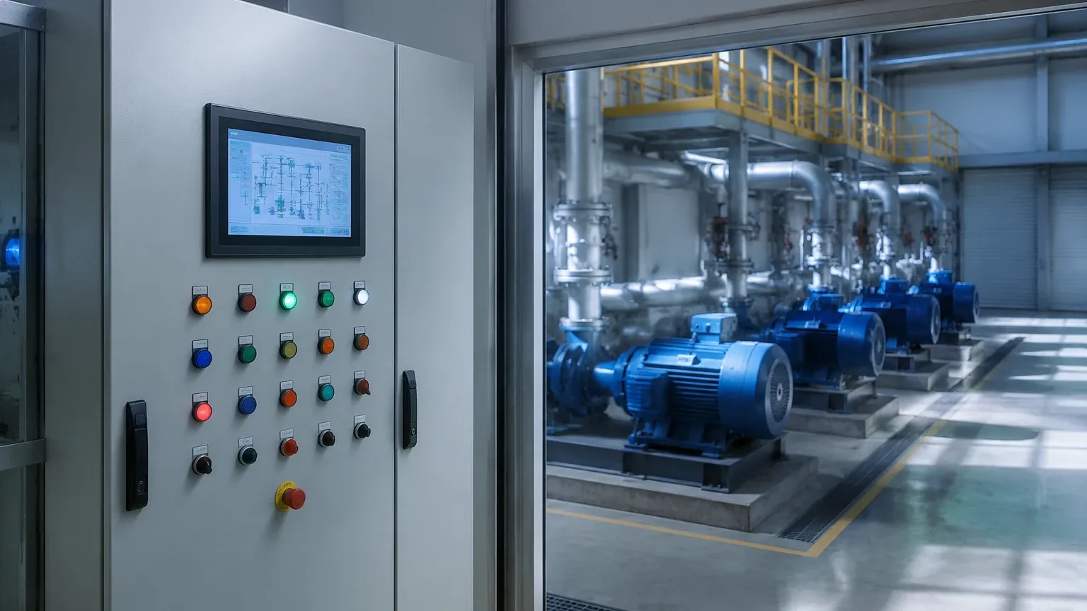
2. Logic Controller (PLC or Dedicated Pump Controller): Processes the level signal and executes the control logic (e.g., starting Pump A at 2.0 meters and stopping it at 0.5 meters).
3. Motor Starters or Variable Frequency Drives (VFDs): Receive the command from the controller to power the pump motors. VFDs are increasingly common as they allow for "soft starts" and variable flow rates, reducing water hammer and energy costs.
4. Human-Machine Interface (HMI): Allows operators to view current levels, adjust setpoints, and monitor pump health.
5. Redundant Safety Overrides: Mechanical float switches that bypass the PLC to stop pumps in a low-level (dry run) condition or start them in a high-level (overflow) condition.
For engineers looking to source high-quality instrumentation for these systems, it is advisable to Review product options and application support from specialized manufacturers like Welk to ensure compatibility with specific industrial fluids.
Control Strategies: Lead/Lag and Duty Cycling
In most pump stations, multiple pumps are installed to provide redundancy and handle peak flow events. The control logic typically follows a "Lead/Lag" configuration:
* Lead Pump: The first pump to start when the level reaches the primary start setpoint.
* Lag Pump: The second pump that starts if the level continues to rise despite the lead pump running, indicating that the inflow exceeds the capacity of a single pump.
* Duty Cycling: The controller alternates which pump acts as the "Lead" pump for each cycle. This ensures even wear across all units, preventing one pump from failing due to over-use while the other seizes due to inactivity.
Selection Criteria for Level Instruments
Choosing the right instrument for pump station control requires an analysis of the fluid characteristics and the physical environment. The table below provides a general comparison for common applications.
| Application Type | Recommended Technology | Primary Reason |
| :— | :— | :— |
| Clean Water Reservoir | Ultrasonic | Cost-effective and reliable in stable environments. |
| Sewage Wet Well | Radar or Hydrostatic | Radar avoids contact with grease/solids; Hydrostatic is unaffected by foam. |
| Chemical Storage | Radar (PTFE Coated) | High resistance to corrosive vapors and high accuracy. |
| Deep Lift Station (>10m) | Hydrostatic | Easier to install and maintain than top-mounted sensors at great heights. |
| Turbulent Process Sump | Radar | Microwaves are more stable than sound waves in turbulent conditions. |
Installation Considerations and Best Practices
Even the most advanced level meter will fail if installed incorrectly. When designing a pump station control layout, consider the following engineering best practices:
1. Avoid Inflow Turbulence
Never mount a level sensor directly above or near the pipe where fluid enters the wet well. The turbulence and air entrainment at the entry point will cause erratic readings. Sensors should be mounted in a "quiet" zone of the tank.
2. Stilling Wells for Hydrostatic Sensors
In applications with high velocity or agitation, submersible hydrostatic transmitters should be housed within a stilling well (a perforated pipe). This protects the sensor from mechanical damage and prevents lateral movement that could strain the cable.
3. Beam Angle Clearance
For ultrasonic and radar sensors, the "beam angle" must be kept clear of obstructions. Ladders, pipes, and pump brackets within the beam path can create false echoes (ghost signals). Modern Welk instruments often feature "False Echo Suppression" software to ignore these fixed objects, but physical clearance remains the preferred solution.
4. Cable Management
Hydrostatic sensors rely on a vented cable to compensate for atmospheric pressure changes. Ensure the vent tube is not kinked and is protected by a desiccant filter to prevent moisture from entering the sensor electronics.
Risks and Limitations in Automated Control
While automation increases efficiency, it introduces specific risks that must be mitigated during the design phase:
* Foam Interference: Heavy foam can absorb ultrasonic signals, leading to a "Loss of Echo" error. In such cases, the controller might assume the tank is empty and fail to start the pumps, leading to an overflow. Radar or hydrostatic sensors are better suited for foamy environments.
* Signal Lag: In very small sumps with high-capacity pumps, the level can change rapidly. The sensor's damping or averaging settings must be adjusted to ensure the control loop responds fast enough to prevent dry-running.
* Build-up and Fouling: In wastewater, fats, oils, and grease (FOG) can build up on ultrasonic transducer faces or clog hydrostatic diaphragms. Regular maintenance schedules are required to clean the sensing surfaces.
Frequently Asked Questions (FAQ)
Q: How often should level sensors in a pump station be calibrated?
A: For most municipal applications, an annual calibration check is sufficient. However, in aggressive industrial chemical applications, quarterly checks may be necessary to ensure accuracy.
Q: Can I use a single sensor to control three different pumps?
A: Yes, a single continuous level transmitter (like a 4-20mA radar) can be used by a PLC to trigger multiple setpoints for Lead, Lag 1, and Lag 2 pumps. However, a redundant high-level float switch is always recommended for safety.
Q: What is the benefit of using Radar over Ultrasonic for wastewater?
A: Radar is generally superior in wastewater because it is unaffected by the methane vapors, humidity, and temperature gradients often found in enclosed wet wells, which can significantly distort ultrasonic sound waves.
Q: What happens if the level sensor fails?
A: A well-designed pump station control system should have a "fail-safe" mode. If the 4-20mA signal is lost (e.g., wire break), the PLC should be programmed to trigger an alarm and potentially run the pumps on a simple timer or based on backup float switches.
Conclusion
Reliable pump station control is a balance of robust hardware and intelligent logic. By understanding the physical principles of level measurement—from the non-contact precision of radar to the rugged simplicity of hydrostatic pressure—engineers can specify systems that minimize downtime and operational costs. For those seeking to optimize their fluid management infrastructure, selecting the appropriate instrumentation from a specialized provider is the first step toward a maintenance-free control solution.