Remote Fuel Monitoring System
Remote Fuel Monitoring System
In industrial operations, fuel represents a significant operational expense and a critical resource for business continuity. A remote fuel monitoring system (RFMS) provides real-time visibility into fuel inventory, consumption rates, and potential anomalies such as leaks or unauthorized withdrawals. These systems transition fuel management from manual sounding or periodic inspections to a data-driven digital framework, allowing facility managers to optimize procurement and ensure equipment uptime.
Implementing an effective monitoring strategy requires an understanding of the underlying sensor technologies, the data transmission architecture, and the environmental factors that influence measurement accuracy. This guide examines the engineering principles and selection criteria essential for deploying a robust fuel monitoring solution.
Fundamentals of Fuel Level Measurement Principles
Before selecting a remote fuel monitoring system, it is necessary to understand the physical principles used to detect fuel levels. Different technologies offer varying degrees of accuracy and suitability based on the fuel type (e.g., diesel, gasoline, or heavy fuel oil) and the tank configuration.
Ultrasonic Level Measurement
Ultrasonic sensors operate on the Time-of-Flight (ToF) principle. The sensor emits high-frequency sound pulses that travel through the air gap in the tank, reflect off the fuel surface, and return to the transducer. The distance is calculated based on the speed of sound. This is a non-contact method, which reduces maintenance requirements since the sensor does not touch the fuel.
Radar Level Measurement
Radar sensors also use ToF but utilize electromagnetic waves instead of sound. High-frequency radar (often 26GHz or 80GHz) is highly effective for fuel because it is unaffected by temperature fluctuations, pressure changes, or the presence of vapors and fumes in the headspace. Guided wave radar (GWR) is a variation where the signal travels along a probe, providing high accuracy even in narrow tanks or those with internal obstructions.
Hydrostatic Pressure Measurement
Hydrostatic transmitters are submerged at the bottom of the tank. They measure the pressure exerted by the liquid column above them. Since pressure is directly proportional to the height of the liquid and its density ($P = \rho gh$), the system can calculate the level. This method is reliable for deep tanks but requires precise knowledge of the fuel's density, which can change with temperature.
Capacitance and Magnetostrictive Principles
Capacitance sensors measure the change in electrical capacitance between two electrodes as fuel displaces air. Magnetostrictive sensors use a float containing a magnet that moves along a sensing rod; they are known for extremely high precision (often within 1 mm) and are frequently used in commercial custody transfer applications.
Core Components of a Remote Fuel Monitoring System
A complete remote fuel monitoring system consists of three primary layers: the sensing layer, the transmission layer, and the application layer.
1. The Sensing Layer: This involves the level sensors (radar, ultrasonic, or hydrostatic) installed on the tanks. In many industrial setups, additional sensors for temperature and flow are integrated to provide a holistic view of fuel health and consumption.
2. The Transmission Layer: This is the "remote" element of the system. Data from the sensors is typically sent to a gateway via wired protocols (RS485/Modbus) or wireless signals (LoRaWAN, Zigbee). The gateway then uploads this data to the cloud or a central server using 4G/5G cellular networks, Ethernet, or satellite links.
3. The Application Layer: This is the user interface where data is processed. It includes dashboards for real-time monitoring, automated alerts for low-level thresholds, and reporting tools for historical consumption analysis.
Selection Criteria for Industrial Fuel Monitoring
Choosing the right system requires balancing technical requirements with budget constraints. The following table provides a comparative overview of common sensor types used in fuel monitoring.
| Technology | Contact Type | Accuracy | Best Use Case | Limitations |
| :— | :— | :— | :— | :— |
| Ultrasonic | Non-contact | ±0.25% to ±0.5% | Standard diesel tanks, stationary storage | Affected by heavy foam or high-pressure vapors |
| Radar (80GHz) | Non-contact | ±1 mm to ±3 mm | High-precision needs, volatile fuels, tall tanks | Higher initial capital expenditure |
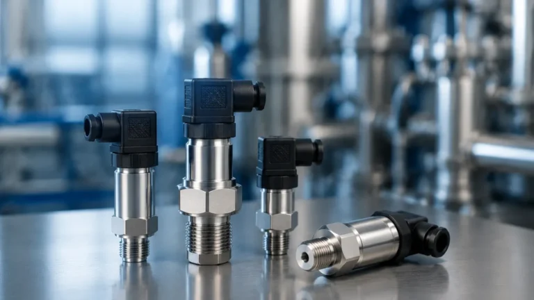
| Hydrostatic | Contact | ±0.1% to ±0.5% | Vented tanks, deep underground storage | Sensitive to fluid density changes |
| Magnetostrictive| Contact | ±0.1 mm | Custody transfer, retail fuel stations | Requires clean fluid; probe length can be a factor |
When evaluating hardware, it is advisable to Review product options and application support to ensure the selected instrumentation aligns with the specific chemical properties of the fuel and the physical dimensions of the storage vessel.
Installation Guidelines and Best Practices
Proper installation is critical to the longevity and accuracy of a remote fuel monitoring system. Engineers must account for both mechanical and electrical considerations.
Positioning and Dead Zones
Every sensor has a "dead zone" or "blocking distance"—an area directly beneath the sensor where measurements cannot be taken. For ultrasonic and radar sensors, the mounting position must ensure the signal does not hit the tank walls or internal baffles, which would cause false echoes. Typically, sensors should be installed at least 200 mm to 500 mm away from the tank wall, depending on the beam angle.
Environmental Protection and Safety
Fuel environments are often classified as hazardous areas. Sensors and gateways must carry appropriate certifications, such as ATEX or IECEx, for use in explosive atmospheres. Furthermore, outdoor installations require an Ingress Protection (IP) rating of at least IP67 or IP68 to withstand rain, dust, and humidity.
Power Supply and Connectivity
Remote sites, such as those used for backup generators or telecommunications towers, may lack stable AC power. In these instances, low-power sensors combined with solar-powered gateways or long-life lithium batteries are necessary. For data transmission, the signal strength of the chosen network (e.g., 4G) must be verified at the specific tank location, especially for underground or indoor tanks where signal attenuation is high.

Limitations and Operational Challenges
While a remote fuel monitoring system offers significant advantages, certain limitations must be managed:
* Temperature Compensation: Fuel expands and contracts with temperature. A drop in level might not indicate a leak but rather a decrease in ambient temperature. Advanced systems use integrated temperature probes to provide "net volume" (compensated to 15°C or 20°C) alongside "gross volume."
* Signal Interference: In metal tanks, internal structures like ladders or heating coils can reflect signals. Selecting a sensor with a narrow beam angle (such as 80GHz radar) or using software-based "false echo suppression" can mitigate this.
* Data Latency: Depending on the transmission interval (e.g., once per hour vs. once per minute), there may be a delay in detecting a sudden fuel theft event. Users must configure alert thresholds carefully to balance battery life with security needs.
Frequently Asked Questions (FAQs)
Q: How often should the sensors be calibrated?
A: Most modern digital sensors like radar and ultrasonic units are factory-calibrated and do not require frequent adjustment. However, a yearly verification against a manual dip-tape reading is recommended for compliance and accuracy assurance.
Q: Can one system monitor multiple tanks?
A: Yes. Most industrial gateways can aggregate data from multiple sensors (e.g., via a Modbus daisy-chain) and transmit all data points through a single cellular or Ethernet connection.
Q: Is it possible to monitor fuel in mobile tankers?
A: Yes, but this requires specialized hardware. Mobile systems typically include GPS modules to track the location of the fuel alongside the level, and sensors must be ruggedized to handle the sloshing and vibration inherent in transport.
Q: What is the typical battery life for a wireless fuel sensor?
A: For IoT-based sensors using LoRaWAN or NB-IoT, battery life can range from 2 to 5 years, depending on the frequency of data transmission and the environmental temperature.
Conclusion
A remote fuel monitoring system is an essential tool for modern industrial resource management. By selecting the appropriate measurement principle—whether it be the precision of radar or the cost-effectiveness of hydrostatic pressure—and ensuring robust data transmission, organizations can significantly reduce the risks of fuel shortages, theft, and environmental incidents. For engineers and procurement officers, the focus should remain on system compatibility, hazardous area compliance, and the ability to integrate the resulting data into existing enterprise management platforms.