Resistive Temperature Sensor
Resistive Temperature Sensor
In industrial process control, the accuracy of level measurement is often inextricably linked to the precision of temperature data. A resistive temperature sensor is a fundamental component used to monitor thermal conditions in tanks, reactors, and pipelines. By leveraging the predictable change in electrical resistance of specific materials in response to temperature fluctuations, these sensors provide the critical data necessary for density compensation, volume correction, and safety monitoring. For engineers and system integrators utilizing advanced instrumentation from the Main Page of industrial catalogs, understanding the mechanics and application of these sensors is essential for maintaining system integrity.
Measurement Principles of Resistive Temperature Sensors
The operation of a resistive temperature sensor is based on the physical property of electrical resistance. All conductive and semi-conductive materials exhibit a change in resistance when their temperature changes. In industrial applications, this phenomenon is categorized into two primary types of sensors: Resistance Temperature Detectors (RTDs) and Thermistors.
The Positive Temperature Coefficient (PTC) in Metals
RTDs typically utilize pure metals such as platinum, nickel, or copper. These metals possess a Positive Temperature Coefficient (PTC), meaning their electrical resistance increases as the temperature rises. This occurs because increased thermal energy causes the metal's atoms to vibrate more vigorously, which in turn impedes the flow of electrons (the electrical current).
The relationship between temperature and resistance in a platinum RTD is highly linear and is defined by the Callendar-Van Dusen equation. For most practical industrial ranges, a simplified linear approximation is often used:
$$R_t = R_0 [1 + \alpha(t – t_0)]$$
Where:
* $R_t$: Resistance at temperature $t$.
* $R_0$: Resistance at reference temperature $t_0$ (usually 0°C).
* $\alpha$: The temperature coefficient of resistance (typically 0.00385 $\Omega/\Omega/°C$ for platinum).
Semiconductor Resistance (Thermistors)
Thermistors are made from ceramic or polymer semiconductor materials. Unlike RTDs, most thermistors used in process control have a Negative Temperature Coefficient (NTC), where resistance decreases as temperature increases. While thermistors offer much higher sensitivity than RTDs, their response is non-linear and follows the Steinhart-Hart equation. They are generally preferred for narrow temperature ranges where high resolution is required.
Types and Materials of Resistive Temperature Sensors
Selecting the right resistive temperature sensor requires an understanding of the material properties and how they align with the specific demands of the process environment.
1. Platinum RTDs (Pt100 and Pt1000)
Platinum is the most common material for industrial resistive temperature sensors due to its chemical inertness, wide temperature range, and exceptional stability.
* Pt100: This sensor has a resistance of 100 ohms at 0°C. It is the global standard for industrial processes.
* Pt1000: This sensor has a resistance of 1000 ohms at 0°C. It provides higher sensitivity and is less affected by the resistance of lead wires, making it ideal for battery-powered or low-power applications.
2. Nickel and Copper RTDs
* Nickel: Offers high sensitivity but has a limited temperature range (typically -80°C to 260°C) and is less linear than platinum.
* Copper: Boasts the most linear resistance-to-temperature relationship but is susceptible to oxidation at higher temperatures, limiting its use to approximately -100°C to 150°C.
3. NTC Thermistors
These are highly sensitive to small temperature changes. They are often used in specialized medical equipment, HVAC systems, and as overheat protection within the electronics of level transmitters.
Integration with Level Measurement Technologies
A resistive temperature sensor is rarely a standalone tool in B2B industrial environments; it is a vital auxiliary for accurate level measurement. Modern level meters, such as those manufactured by Welk, often incorporate temperature sensing to refine their primary readings.
Hydrostatic Level Compensation
Hydrostatic level transmitters measure the pressure exerted by a liquid column. However, the density of a liquid changes with temperature. If the temperature of a chemical in a storage tank rises, the liquid expands and its density decreases. Without a resistive temperature sensor to provide real-time thermal data, the hydrostatic transmitter would report an incorrect level because the pressure per unit of height has changed. By integrating temperature data, the control system can calculate the "compensated level" accurately.
Radar and Ultrasonic Velocity Correction
In non-contact level measurement, such as ultrasonic sensors, the speed of the sound wave is heavily dependent on the temperature of the vapor space. A change of just 1°C can result in a significant measurement error over long distances. Resistive temperature sensors mounted within the sensor housing or the tank headspace allow the transmitter to adjust the time-of-flight calculation, ensuring precision regardless of seasonal or process-driven temperature shifts.
Practical Selection Table
When evaluating a resistive temperature sensor for your project, consider the following technical benchmarks:
| Feature | Pt100 RTD | Pt1000 RTD | NTC Thermistor |
| :— | :— | :— | :— |
| Temperature Range | -200°C to +850°C | -200°C to +600°C | -50°C to +250°C |
| Accuracy | High (Class AA, A, B) | High | Medium to High |
| Linearity | Excellent | Excellent | Poor (Exponential) |
| Sensitivity | 0.385 $\Omega/°C$ | 3.85 $\Omega/°C$ | Very High (e.g., 5% per °C) |
| Long-term Stability | Excellent | Excellent | Moderate |
| Cost | Moderate | Moderate | Low |
Installation and Wiring Considerations
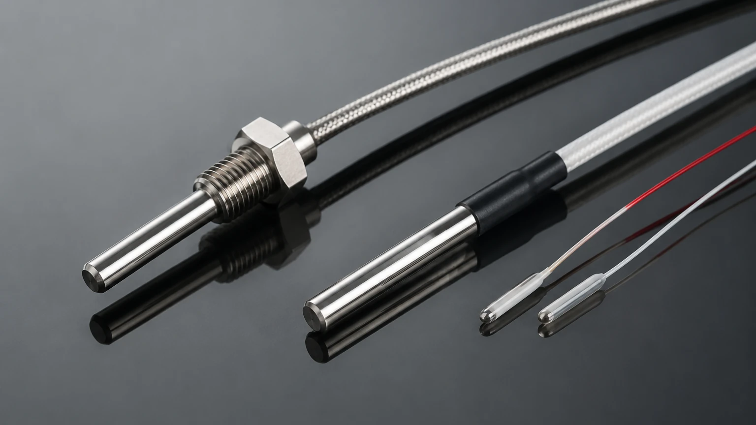
The accuracy of a resistive temperature sensor is not solely dependent on the sensor itself but also on how it is connected to the control system. Lead wire resistance is a common source of error that must be mitigated.
Wiring Configurations
1. 2-Wire Configuration: The simplest but least accurate. The resistance of the lead wires is added directly to the sensor resistance, creating a positive error in temperature reading. It is only suitable for very short distances or when high precision is not required.
2. 3-Wire Configuration: The industrial standard. A third wire allows the measurement electronics to calculate and subtract the lead wire resistance, assuming all three wires have identical resistance. This is the most common setup for RTDs in level measurement systems.
3. 4-Wire Configuration: The most accurate method. It uses two wires to carry the excitation current and two separate wires to measure the voltage drop across the sensor. This completely eliminates the influence of lead wire resistance and is used in laboratory and high-precision custody transfer applications.
Thermowell Usage
In pressurized tanks or corrosive environments, the resistive temperature sensor should be installed inside a thermowell. A thermowell is a cylindrical fitting that protects the sensor from the process fluid and mechanical stress. While it facilitates sensor replacement without draining the tank, it does introduce a thermal lag (slower response time) that must be accounted for in the process control loop.
Limitations and Common Risks
While highly reliable, resistive temperature sensors are subject to specific operational risks:
* Self-Heating: To measure resistance, a small current must pass through the sensor. This current generates heat ($I^2R$). If the current is too high or the medium being measured has poor thermal conductivity (like stagnant air), the sensor will report a temperature higher than the actual process temperature. Typically, excitation currents should be kept below 1 mA.
* Mechanical Stress and Vibration: RTDs, particularly wire-wound types, are sensitive to high-vibration environments. Excessive vibration can cause the internal platinum wires to fatigue and break. In such cases, thin-film RTDs are preferred due to their more robust construction.
* Drift: Over time, exposure to extreme temperatures or mechanical shock can cause the sensor's resistance-temperature curve to shift. Regular calibration against a known standard is necessary for critical B2B applications.
* Insulation Resistance: If the seal of the sensor probe is compromised, moisture can enter and decrease the insulation resistance between the sensor element and the outer sheath. This creates a parallel resistance path, leading to erroneously low temperature readings.
Frequently Asked Questions (FAQs)
Q: Can I use a resistive temperature sensor for cryogenic applications?
A: Yes, platinum RTDs are excellent for cryogenic measurements down to -200°C. Special cryogenic-grade sensors are available that are designed to handle the thermal contraction of materials at these extremes.
Q: How do I know if my sensor is failing?
A: Common signs of failure include erratic readings (fluctuating wildly), a "frozen" reading that does not change with process conditions, or an "Open Circuit" error on your transmitter. You can test the sensor with a multimeter by measuring the resistance and comparing it to a standard PT100/PT1000 chart for the current ambient temperature.
Q: Why choose an RTD over a thermocouple?
A: RTDs offer much higher accuracy and stability over time compared to thermocouples. While thermocouples are cheaper and can measure higher temperatures (above 1000°C), they are prone to drift and require cold-junction compensation.
Conclusion
A resistive temperature sensor is a cornerstone of precise industrial instrumentation. Whether it is used for direct process monitoring or as a compensation tool for level measurement, its reliability and accuracy are paramount. By selecting the appropriate material, understanding the wiring requirements, and protecting the sensor from environmental stressors, engineers can ensure long-term stability in their control systems. For those seeking integrated solutions that combine temperature and level sensing technology, exploring the advanced options on the Main Page is the recommended next step for optimizing process efficiency and safety.