Rockwell Automation Fair 2026
Rockwell Automation Fair 2026
As the industrial landscape moves toward deeper digital integration and autonomous operations, events like the Rockwell Automation Fair 2026 serve as pivotal touchpoints for engineers and plant managers. While the fair showcases the latest in programmable logic controllers (PLCs), distributed control systems (DCS), and industrial IoT software, the foundational layer of any automation architecture remains the field instrumentation. Accurate level measurement is critical for the success of the high-level control strategies discussed at such forums.
For professionals attending or tracking the developments of the Rockwell Automation Fair 2026, understanding the intersection between advanced sensing hardware and control ecosystems is essential. This guide provides a technical overview of level measurement technologies, their integration into automated environments, and the criteria necessary for selecting reliable instrumentation for water treatment, chemical processing, and oil and gas applications.
Core Measurement Principles in Industrial Level Sensing
Before evaluating the high-level software solutions presented at major automation events, one must understand the physics governing the sensors that provide the data. Level measurement can be broadly categorized into non-contact and contact methods, each utilizing distinct physical principles.
Radar Level Measurement (Time of Flight)
Radar level meters, particularly those operating at 80 GHz, represent the current gold standard for precision. These instruments utilize the Time of Flight (ToF) principle. The sensor emits a high-frequency electromagnetic pulse (or a continuous wave in FMCW systems) that travels to the surface of the medium and reflects back to the antenna.
Because electromagnetic waves travel at the speed of light, radar is virtually unaffected by changes in temperature, pressure, or vacuum conditions. The precision of an 80 GHz radar allows for a narrow beam angle, which is crucial in tanks with internal obstructions like agitators or heating coils. In the context of the Rockwell Automation Fair 2026, the focus on "Digital Twins" relies heavily on the high-accuracy data provided by these radar units to create a mirror image of physical inventory in real-time.
Ultrasonic Level Sensing
Ultrasonic sensors utilize sound waves rather than electromagnetic waves. The transducer emits an ultrasonic pulse that reflects off the surface of the liquid or solid. The distance is calculated based on the time it takes for the echo to return, adjusted for the speed of sound in the specific medium (usually air).
While cost-effective, ultrasonic measurement is sensitive to the composition of the vapor space. Changes in air temperature, heavy dust, or the presence of vapors that alter the speed of sound can introduce errors. However, for many water treatment applications and open-channel flow measurements, ultrasonic sensors remain a robust and reliable choice.
Hydrostatic Level Measurement
Hydrostatic transmitters measure level by detecting the pressure exerted by a liquid column at a specific point. The principle is based on the formula: *P = ρgh* (Pressure = Density × Gravity × Height). By measuring the pressure at the bottom of a tank and knowing the density of the fluid, the transmitter can accurately calculate the height of the liquid.
This method is highly reliable for vented tanks but requires compensation for pressurized vessels. It is a contact-based method, meaning the sensor diaphragm is exposed to the process media, necessitating careful material selection for corrosive environments.
Magnetic Level Gauges
Magnetic level gauges (MLGs) provide both local visual indication and, when equipped with transmitters, electronic feedback to the control system. They operate on the principle of buoyancy and magnetism. A float containing a permanent magnet moves with the liquid level inside a bypass chamber. Outside the chamber, magnetic flags or a follower indicate the level. For automated systems, a magnetostrictive or reed-switch transmitter is strapped to the chamber to convert the float position into a 4-20mA or digital signal.
Integrating Instrumentation with Rockwell Automation Ecosystems
At the Rockwell Automation Fair 2026, a major theme is the seamless flow of data from the "Edge to the Enterprise." For level measurement, this means moving beyond simple analog signals to intelligent, networked instrumentation.
Communication Protocols
Modern level meters, such as those found on the Main Page of leading manufacturers, support a variety of communication protocols:
* 4-20mA HART: The most common standard, allowing digital configuration and diagnostics to be superimposed on the traditional analog loop.
* EtherNet/IP: Highly relevant for Rockwell environments, allowing instruments to connect directly to the control network without the need for intermediate I/O modules.
* Modbus RTU/TCP: Often used in smaller systems or for integration with third-party HMI and SCADA platforms.
Data Integrity and Diagnostics
Advanced level meters now provide diagnostic data that goes beyond the level reading itself. Signal strength, signal-to-noise ratios, and electronics temperature can be monitored. In a predictive maintenance framework—a key topic at the Rockwell Automation Fair 2026—this data allows plant operators to identify probe buildup or sensor degradation before a failure occurs, reducing unplanned downtime.
Practical Selection Table for Level Technologies
Choosing the right technology requires balancing process conditions with budget and accuracy requirements. The following table provides a general guideline for selection.
| Technology | Typical Accuracy | Max Range | Contact/Non-Contact | Best Use Case |
| :— | :— | :— | :— | :— |
| 80 GHz Radar | ±1 mm | Up to 120m | Non-Contact | High-precision chemical/oil storage, turbulent surfaces. |
| Ultrasonic | ±0.25% of range | Up to 30m | Non-Contact | Water/Wastewater, open channels, sumps. |
| Hydrostatic | ±0.1% to 0.5% | Dependent on pressure | Contact | Deep wells, vented tanks, constant density liquids. |
| Magnetic Gauge | ±5 mm to 10 mm | Up to 6m (standard) | Contact (Float) | High-pressure boilers, toxic media, visual backup needed. |
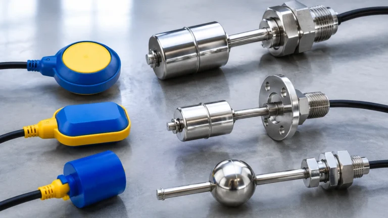
| Level Switch | N/A (Point level) | N/A | Contact | Overfill protection, pump dry-run prevention. |

Installation Considerations and Common Risks
Even the most advanced sensor will fail if installed incorrectly. Engineering teams must consider several physical factors when integrating level measurement into an automated system.
Beam Angle and Obstructions
For radar and ultrasonic sensors, the "beam angle" determines the footprint of the signal at the surface of the material. If the beam hits a ladder, agitator, or the tank wall, it can create a false echo. Modern sensors use software algorithms to "map out" these static reflections, but proper positioning is always the first line of defense. Generally, sensors should be installed at least 200mm to 500mm away from the tank wall to avoid interference.
The "Dead Zone" (Blocking Distance)
All non-contact sensors have a minimum distance near the sensor face where they cannot accurately measure. This is known as the dead zone or blocking distance. For ultrasonic sensors, this is typically 0.25m to 0.5m. For radar, it is much smaller (often <0.1m). If the liquid level enters this zone, the sensor may report an incorrect high level or go into an error state.
Media Properties: Dielectric Constant (Dk)
For radar measurement, the Dielectric Constant (Dk) of the medium is critical. Low Dk fluids (like liquefied gases or some oils) reflect electromagnetic waves poorly. In these cases, a guided wave radar or a high-sensitivity 80 GHz radar is required to ensure a stable signal return. If the Dk is below 1.4, standard radar may struggle without specialized antennas.
Environmental Factors
* Foam: Heavy, dense foam can absorb ultrasonic and radar signals. In such cases, hydrostatic or magnetic level gauges are often more reliable.
* Vapor and Condensation: Condensation on the sensor face can attenuate signals. Choosing a sensor with a PTFE or drip-off antenna design helps mitigate this risk.
* Turbulence: Rapidly moving surfaces can scatter signals. Signal damping and averaging algorithms in the transmitter can help smooth the output, but mechanical stilling wells may be necessary in extreme cases.
Information to Confirm Before Implementation
As you prepare for the Rockwell Automation Fair 2026 and plan your next instrumentation upgrade, ensure your project team has confirmed the following technical details:
1. Process Media Profile: What is the chemical composition, density, and dielectric constant? Is the media corrosive or abrasive?
2. Vessel Geometry: Provide a detailed drawing including the height, diameter, and the location of all internal obstructions.
3. Operating Conditions: Confirm the maximum and minimum temperature and pressure. Instrumentation must be rated for the extreme limits, not just the nominal operating point.
4. Integration Requirements: Which communication protocol is required for the PLC/DCS? Does the instrument need to be part of a Safety Instrumented System (SIS) with a SIL rating?
5. Certification Needs: Are there requirements for Explosion Proof (Ex d) or Intrinsically Safe (Ex i) ratings based on the hazardous zone classification?
Frequently Asked Questions (FAQ)
Q: Can I use an ultrasonic sensor for measuring solids in a silo?
A: Yes, but with caution. Solids often create dust and have uneven surfaces that scatter sound waves. High-power ultrasonic sensors designed for solids can work, but 80 GHz radar is generally preferred for its ability to penetrate dust and its narrower beam.
Q: Why is 80 GHz radar considered better than 26 GHz radar?
A: The higher frequency allows for a much smaller antenna and a narrower beam angle (as low as 3 degrees). This makes it easier to install in small nozzles and reduces the likelihood of the signal hitting internal tank obstructions.
Q: How do I handle level measurement in a tank with heavy agitation?
A: There are two main approaches. One is to use a non-contact radar with a fast response time and signal tracking algorithms. The other is to use a contact method like a magnetic level gauge or a hydrostatic transmitter, which are less affected by surface turbulence.
Q: Is it possible to integrate these sensors directly into a Rockwell PlantPAx system?
A: Absolutely. By using EtherNet/IP enabled transmitters or HART-to-EtherNet/IP gateways, level data and diagnostics can be pulled directly into the PlantPAx environment, allowing for enhanced visualization and asset management.
By focusing on the physical realities of the process and the technical specifications of the hardware, engineers can ensure that the sophisticated automation strategies discussed at the Rockwell Automation Fair 2026 are supported by accurate, reliable, and high-integrity field data. For more detailed product specifications and application support, engineers are encouraged to Review product options and application support to find the right fit for their specific industrial challenges.