K Factor Flow Meter
K Factor Flow Meter
In industrial process control and fluid management, the accuracy of flow measurement is a fundamental requirement for operational efficiency, safety, and billing. For many types of flow measurement devices—specifically those that generate a frequency or pulse output—the K-factor is the most critical parameter. A k factor flow meter relies on this calibration constant to convert raw electronic signals into meaningful volumetric or mass flow data.
Understanding the derivation, application, and maintenance of the K-factor is essential for engineers and technicians working with liquid and gas systems. This guide provides a technical overview of K-factors, their role in different flow meter technologies, and best practices for ensuring measurement integrity.
Measurement Principles of the K-Factor
The K-factor is defined as the number of pulses produced by a flow meter per unit of volume (or mass) of fluid passing through it. It is the scaling factor that bridges the gap between the mechanical or physical action of the meter and the digital readout of the flow computer.
The Fundamental Equation
The relationship between the output frequency of a flow meter and the flow rate is expressed by the following formula:
Q = f / K
Where:
* Q = Volumetric flow rate (e.g., liters per minute, m³/h).
* f = Frequency of the pulse output (pulses per second or Hertz).
* K = The K-factor (pulses per unit volume, such as pulses/liter).
For example, if a turbine flow meter has a K-factor of 500 pulses per liter and the sensor detects a frequency of 1,000 Hz (1,000 pulses per second), the flow rate is 2 liters per second (120 liters per minute).
How K-Factors are Determined
K-factors are typically determined through factory calibration under controlled conditions. Manufacturers use high-precision "master meters" or gravimetric (weight-based) systems to measure a known quantity of fluid while recording the total number of pulses generated by the meter under test. Because mechanical tolerances and sensor sensitivities vary slightly between units, every individual meter—even those of the same model and size—will have a unique K-factor.
Types of Flow Meters Utilizing K-Factors
While many flow meters exist, those that output a pulse or frequency signal are the primary users of K-factors.
1. Turbine Flow Meters
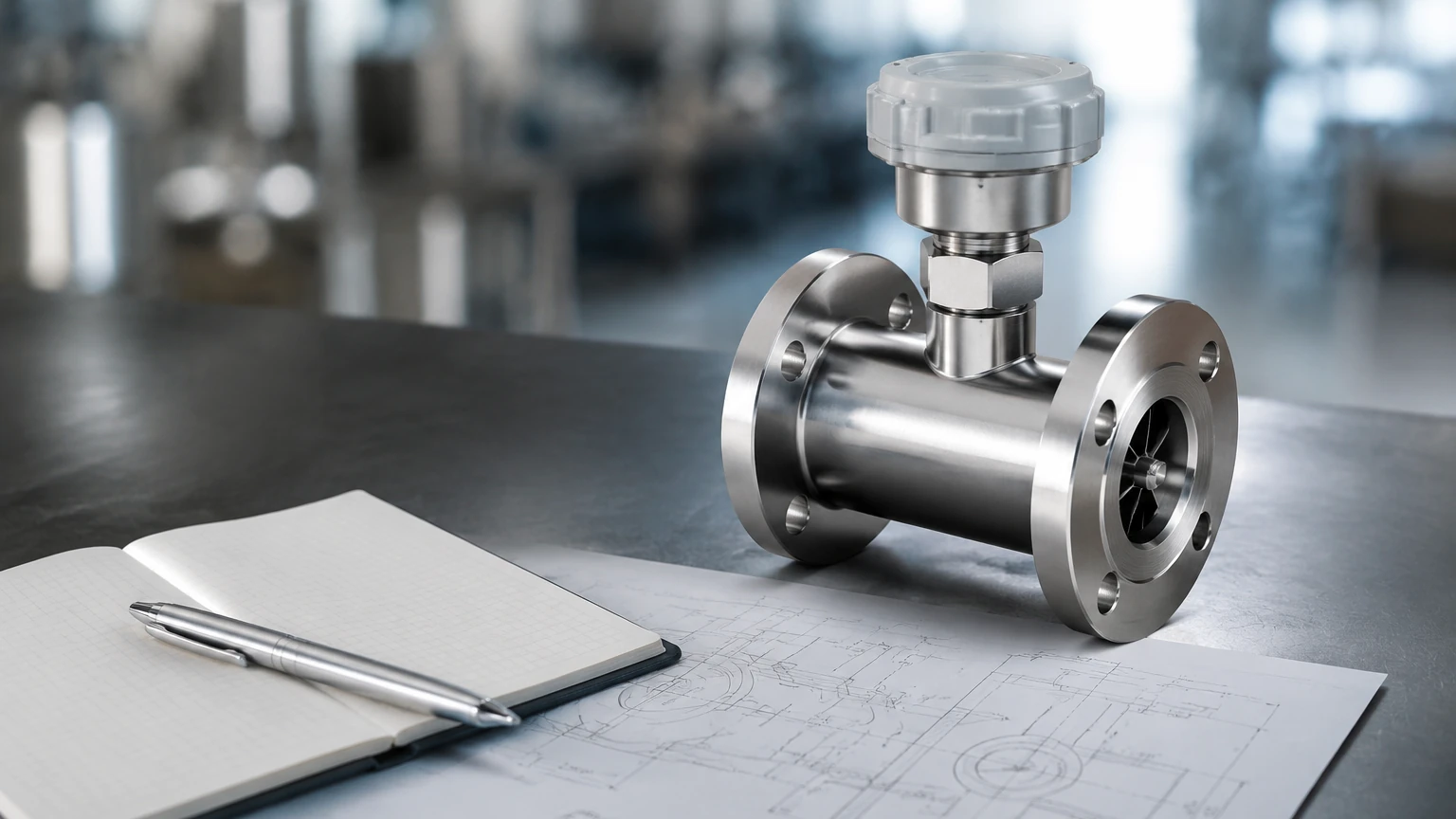
As fluid passes through the meter, it causes a rotor to spin. Each rotor blade passing a magnetic pickup generates an electrical pulse. The K-factor represents the relationship between the rotor's revolutions and the volume of fluid displaced. These are highly accurate but sensitive to changes in fluid viscosity.
2. Positive Displacement (PD) Meters
PD meters, such as oval gear or nutating disc meters, trap a fixed volume of fluid in a chamber and move it from the inlet to the outlet. Each rotation of the internal mechanism corresponds to a specific volume. Sensors detect these rotations to produce pulses. K-factors for PD meters tend to be very stable across varying viscosities.
3. Vortex Flow Meters
Vortex meters work on the von Kármán effect, where fluid passing a bluff body creates alternating vortices. The frequency of these vortices is proportional to the flow velocity. The K-factor here converts the vortex frequency into volume.
4. Paddlewheel and Impeller Meters
Often used in water treatment and irrigation, these meters use a rotating wheel in the flow stream. While less precise than turbine meters, they provide a cost-effective solution where a K-factor is used to scale the output for PLC (Programmable Logic Controller) integration.
Practical Selection Table
When selecting a flow meter based on K-factor stability and application requirements, consider the following technical comparison:
| Meter Type | Typical Fluid | K-Factor Stability | Accuracy (Linearity) | Primary Limitation |
| :— | :— | :— | :— | :— |
| Turbine | Low-viscosity liquids, gases | High (in linear range) | ±0.25% to ±0.5% | Viscosity sensitive |
| Oval Gear (PD) | Oils, chemicals, viscous fluids | Very High | ±0.5% | High pressure drop |
| Vortex | Steam, gases, water | High | ±1.0% | Minimum Reynolds number required |
| Paddlewheel | Water, non-viscous chemicals | Moderate | ±1.0% to ±4.0% | Requires full pipe profile |
Factors Affecting K-Factor Accuracy
A K-factor is not a static "set and forget" number. Several environmental and physical factors can cause the actual performance of the meter to deviate from its factory-calibrated K-factor.
Viscosity and Reynolds Number
For turbine flow meters, the K-factor is highly dependent on the Reynolds number (a dimensionless value representing the ratio of inertial forces to viscous forces). If the fluid's viscosity increases (e.g., oil cooling down), the K-factor may shift, particularly at lower flow rates. Engineers often use a "Universal Viscosity Curve" (UVC) to adjust the K-factor based on the fluid's kinematic viscosity.
Temperature and Pressure
Changes in temperature can cause the physical dimensions of the flow meter housing and internal components to expand or contract. For high-precision applications, a temperature correction factor is applied to the K-factor. Similarly, high pressure can compress certain fluids (gases) or slightly deform the meter body, affecting the pulse-to-volume ratio.
Wear and Mechanical Fatigue
In mechanical meters (turbine, PD, paddlewheel), bearing wear or erosion of the rotor blades will gradually change the K-factor over time. Periodic recalibration is necessary to ensure the meter remains within its specified accuracy class.
Installation Considerations
To ensure the K-factor remains valid in a field installation, the following engineering guidelines should be followed:
1. Straight Pipe Runs: Most k factor flow meters (especially turbine and vortex) require a specific length of straight pipe upstream and downstream to eliminate turbulence and swirl. A common standard is 10 diameters (10D) upstream and 5 diameters (5D) downstream.
2. Avoid Cavitation: For liquid applications, the backpressure must be maintained high enough to prevent cavitation. Cavitation creates vapor bubbles that the meter counts as fluid volume, leading to an artificially high pulse count and an inaccurate K-factor.
3. Fluid Cleanliness: Particulates can damage rotors or clog PD meter gears. Installing a strainer (typically 40 to 100 mesh) upstream of the meter is highly recommended to protect the calibration integrity.
4. Orientation: While some meters can be installed in any orientation, many require horizontal mounting to ensure the bearings are loaded correctly and the pipe remains full.
Integration with Level Measurement Systems
In many industrial setups, flow measurement is used in conjunction with level measurement to provide a complete picture of tank inventory and process mass balance. While flow meters track the movement of fluid into or out of a vessel, level instruments—such as radar level meters or ultrasonic sensors—provide the absolute verification of the volume remaining.
For instance, in a chemical blending tank, a k factor flow meter might measure the precise dosage of additives, while a high-frequency radar level transmitter monitors the total tank level to prevent overfills. For engineers designing these integrated systems, it is helpful to Review product options and application support to ensure that both flow and level instruments are compatible with the process media and communication protocols (such as Modbus or HART).
Frequently Asked Questions (FAQ)
Why does my flow meter have multiple K-factors listed?
Many high-end meters provide a "linearization table." This is a list of different K-factors for different flow ranges. Since no meter is perfectly linear, using a table allows the flow computer to pick the most accurate K-factor based on the current frequency output.
Can I calculate a K-factor manually?
If the factory calibration certificate is lost, you can perform a field calibration. Measure a known volume (e.g., into a 200-liter drum) and record the total pulses. Divide the total pulses by the volume to find the field K-factor. However, factory calibration is always preferred for high-accuracy requirements.
What is the difference between a K-factor and a Scaling Factor?
They are often used interchangeably, but technically, the K-factor is the pulses per unit (e.g., 100 pulses/gal), while a scaling factor might be the inverse (e.g., 0.01 gallons/pulse) used by a PLC to increment a totalizer.
How often should a k factor flow meter be recalibrated?
This depends on the fluid and the meter type. For non-lubricating or abrasive fluids, annual calibration is standard. For clean, lubricating fluids like refined oil, the interval may be extended to every two or three years.
Summary of Best Practices
To maximize the utility of a k factor flow meter, engineers should:
* Always use the specific K-factor provided on the manufacturer's calibration certificate for that specific serial number.
* Ensure the flow computer or PLC is programmed with the correct units (e.g., pulses per liter vs. pulses per gallon) to avoid massive calculation errors.
* Monitor the Reynolds number if the process involves fluctuating temperatures or varying fluid types.
* Cross-reference flow data with level measurement instruments to detect potential meter drift or mechanical failure early.
By adhering to these principles and maintaining a rigorous calibration schedule, the K-factor remains a reliable tool for precision fluid management across the water treatment, chemical, and oil and gas industries.