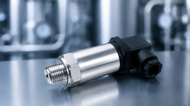
Rtd Thermal Sensor
Rtd Thermal Sensor
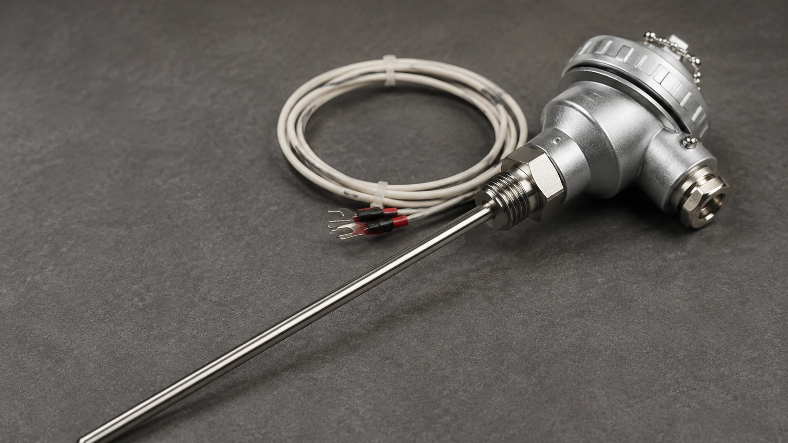
In the landscape of industrial process control, the RTD thermal sensor (Resistance Temperature Detector) stands as one of the most reliable and precise instruments for monitoring temperature. Unlike thermocouples, which rely on the Seebeck effect between two dissimilar metals, an RTD operates on the principle that the electrical resistance of a metal increases predictably as its temperature rises. This linear and stable relationship makes the RTD a preferred choice for applications requiring high accuracy and long-term stability, particularly in water treatment, chemical processing, and oil and gas industries.
For engineers and plant managers, understanding the nuances of temperature measurement is not merely an exercise in thermal monitoring; it is often a prerequisite for accurate level measurement. Temperature fluctuations can significantly impact the density of fluids and the velocity of signals, making the integration of high-quality thermal sensors a critical component of any automated system. To explore how these sensors complement a full range of industrial instrumentation, you can visit the Main Page for detailed product specifications and system integration options.
Measurement Principles of RTD Sensors
The fundamental operation of an RTD thermal sensor is based on the Temperature Coefficient of Resistance (TCR). Most industrial RTDs utilize platinum, a noble metal chosen for its chemical inertness, wide temperature range, and excellent linearity. The relationship between temperature and resistance is typically defined by the Callendar-Van Dusen equation, though for most practical industrial applications within a standard range, the relationship is nearly linear.
The most common standard is the Pt100, which signifies a platinum element with a resistance of exactly 100 ohms at 0°C (32°F). As the temperature increases, the resistance increases at a standardized rate—most commonly an alpha coefficient of 0.00385 Ω/Ω/°C. For example, at 100°C, a standard Pt100 sensor will have a resistance of approximately 138.51 ohms.
Other variations include the Pt1000, which has a base resistance of 1000 ohms at 0°C. The higher resistance of the Pt1000 makes it less sensitive to the resistance of the lead wires, which is particularly beneficial in two-wire configurations or battery-powered applications where power consumption must be minimized.
Types of RTD Construction
When selecting an RTD thermal sensor, the construction method is as important as the material itself. There are two primary types of RTD elements used in industrial environments:
1. Thin-Film RTD Elements
Thin-film elements are produced by depositing a very thin layer of platinum onto a ceramic substrate. This layer is then laser-trimmed to achieve the desired resistance. The entire assembly is encapsulated in glass or epoxy to protect the platinum film. These sensors are highly vibration-resistant, have a fast response time, and are generally more cost-effective. However, they are typically limited to lower temperature ranges (up to 500°C) compared to wire-wound versions.
2. Wire-Wound RTD Elements
Wire-wound elements consist of a fine platinum wire coiled around a ceramic or glass mandrel. This design allows the wire to expand and contract freely with temperature changes, minimizing mechanical strain that can cause resistance shifts. Wire-wound RTDs offer the highest accuracy and can operate at much higher temperatures (up to 850°C), but they are more fragile and sensitive to high-vibration environments.
Wiring Configurations and Lead Wire Compensation
Because an RTD is a resistance-based sensor, the resistance of the copper wires connecting the sensor to the control system can introduce measurement errors. To mitigate this, three primary wiring configurations are used:
* 2-Wire Configuration: This is the simplest but least accurate method. The resistance of the lead wires is added directly to the sensor resistance, leading to a higher temperature reading than actual. It is only recommended for short distances or when high precision is not required.
* 3-Wire Configuration: This is the industry standard for most B2B applications. It uses a third wire to measure the lead resistance and subtracts it from the total resistance. This provides a balance between cost and accuracy, effectively compensating for lead wire resistance as long as all three wires have the same resistance and are at the same temperature.
* 4-Wire Configuration: Used in laboratory settings or high-precision industrial processes, the 4-wire configuration completely eliminates the effect of lead wire resistance. It uses two wires to carry the excitation current and two independent wires to measure the voltage drop across the RTD element.
The Synergy Between Temperature and Level Measurement
In industrial automation, level measurement and temperature measurement are intrinsically linked. For a manufacturer like Welk, providing accurate level data often requires simultaneous temperature monitoring. Here is how an RTD thermal sensor impacts various level measurement technologies:
Hydrostatic Level Transmitters
Hydrostatic sensors measure the pressure exerted by a liquid column. However, pressure is a function of both height and density. Since liquid density changes with temperature, a hydrostatic system without temperature compensation will report inaccurate levels as the process fluid warms or cools. Integrating an RTD allows the PLC (Programmable Logic Controller) to calculate the real-time density and provide a corrected level reading.
Radar and Ultrasonic Level Meters
For non-contact measurement, the environment in the tank's headspace matters. In radar level measurement, the dielectric constant of the gas phase can be influenced by temperature and pressure. In ultrasonic systems, the speed of sound is directly proportional to the square root of the absolute temperature. Without a precise RTD thermal sensor to monitor the headspace temperature, ultrasonic level meters can experience errors of approximately 0.17% per degree Celsius change.
Practical Selection Criteria
Choosing the right RTD requires a comparison of process conditions against sensor specifications. The following table provides a general guideline for evaluating RTD options:
| Feature | Pt100 (Thin-Film) | Pt100 (Wire-Wound) | Pt1000 (Thin-Film) |
| :— | :— | :— | :— |
| Temperature Range | -50°C to +500°C | -200°C to +850°C | -50°C to +500°C |
| Accuracy Class | Class A / Class B | Class AA (1/3 DIN) | Class A / Class B |
| Vibration Resistance | Excellent | Moderate | Excellent |
| Response Time | Fast | Moderate | Fast |
| Common Application | General Industrial | Lab / High Temp | Battery Powered / HVAC |
| Cost | Low to Moderate | High | Moderate |
Accuracy Classes
RTDs are categorized by their tolerance levels according to international standards (IEC 60751):
* Class AA (1/3 DIN): Tolerance of ±(0.1 + 0.0017 |t|) °C.
* Class A: Tolerance of ±(0.15 + 0.002 |t|) °C.
* Class B: Tolerance of ±(0.30 + 0.005 |t|) °C.
Installation Considerations and Best Practices
To ensure the longevity and accuracy of an RTD thermal sensor, proper installation is paramount. Engineers should consider the following factors:
1. Thermowell Selection: In high-pressure or corrosive environments, the RTD should be installed inside a thermowell. This allows for sensor replacement without breaking the process seal and protects the element from mechanical damage. The material of the thermowell (e.g., 316 Stainless Steel, Hastelloy) must be compatible with the process fluid.
2. Immersion Depth: To avoid "stem conduction" errors (where heat travels along the sensor sheath to the outside environment), the sensor should be immersed to a depth at least 10 times the diameter of the protection tube.
3. Self-Heating: RTDs require an excitation current to operate. This current generates a small amount of heat within the element. To maintain accuracy, the excitation current should be kept as low as possible (typically 1 mA or less).
4. Environmental Shielding: In industrial plants with heavy machinery, electromagnetic interference (EMI) can distort resistance readings. Using shielded, twisted-pair cabling and ensuring proper grounding of the instrument housing is essential.
Limitations and Common Risks
While the RTD thermal sensor is highly accurate, it is not suitable for every application. Its primary limitations include:
* Response Time: Compared to thermocouples, RTDs generally have a slower response to rapid temperature steps due to their larger thermal mass and the need for protective sheathing.
* Cost: The use of platinum and the complexity of construction make RTDs more expensive than thermocouples, especially for high-temperature models.
* Fragility: While thin-film versions are robust, wire-wound RTDs can be damaged by extreme mechanical shock or high-frequency vibration.
* Self-Heating Errors: If the controller provides too much current, the sensor will report a temperature higher than the actual process temperature.
Frequently Asked Questions (FAQs)
Q: When should I choose a Pt1000 over a Pt100?
A: A Pt1000 is preferred when using a 2-wire configuration over long distances, as the higher base resistance makes the lead wire resistance less significant. It is also ideal for low-power, battery-operated devices.
Q: How often should an RTD thermal sensor be calibrated?
A: For most industrial processes, annual calibration is standard. However, in critical chemical or pharmaceutical applications, semi-annual or quarterly verification may be required to ensure compliance with quality standards.
Q: Can an RTD be used in cryogenic applications?
A: Yes, specifically wire-wound platinum RTDs are excellent for cryogenic temperatures down to -200°C. Special construction is required to ensure the materials do not become brittle or fail due to thermal contraction.
Q: What is the difference between an RTD and a Thermistor?
A: While both change resistance with temperature, RTDs use metals (like platinum) and have a linear relationship over a wide range. Thermistors use ceramic or polymer materials, have a non-linear relationship, and are typically used for a narrow temperature range with very high sensitivity.
By carefully selecting and installing the appropriate RTD thermal sensor, industrial operators can ensure the precision of their thermal data and, by extension, the reliability of their level measurement and process control systems. For more information on integrated measurement solutions, please refer to the Main Page.