Thickener Optimizer
Thickener Optimizer
In industrial liquid-solid separation, the thickener is a pivotal component used to increase the concentration of a slurry by allowing solids to settle under gravity. A thickener optimizer is a comprehensive control strategy or system designed to maximize the efficiency of this process. By stabilizing the underflow density and ensuring overflow clarity, an optimizer reduces reagent costs, such as flocculants, and improves the performance of downstream equipment like filters or kilns.
Achieving this level of optimization requires precise, real-time data from a variety of sensors. Without accurate measurement of the bed level, bed mass, and overflow turbidity, a thickener optimizer cannot function effectively. This article explores the instrumentation and engineering principles necessary to implement a robust thickener optimization strategy.
The Role of Level Measurement in Thickener Optimization
Thickening is a continuous process where the feed slurry enters a central well, is treated with chemicals (flocculants) to promote particle grouping, and then settles into a compacted bed at the bottom. The "optimizer" relies on three primary variables: the interface level (where the clear liquid meets the settling solids), the bed level (the compacted solids), and the total liquid level.
Reliable level measurement serves as the eyes of the thickener optimizer. If the bed level is too low, the underflow density will be insufficient, leading to wasted energy in downstream pumping and processing. Conversely, if the bed level is too high, the solids may overflow into the clean water stream or stall the rake mechanism, causing significant mechanical damage and plant downtime.
For engineers looking to upgrade their control systems, reviewing specialized instrumentation on the Main Page of a professional manufacturer provides a baseline for available technologies.
Core Measurement Principles for Thickener Control
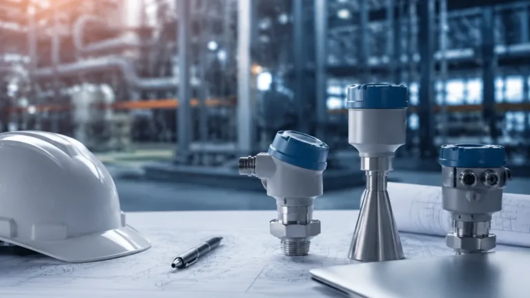
Before selecting a thickener optimizer solution, it is essential to understand the measurement principles behind the sensors that feed these systems. Each technology has specific strengths depending on the slurry characteristics and the environmental conditions of the tank.
Ultrasonic Level Measurement
Ultrasonic sensors operate on the time-of-flight principle. The sensor emits a high-frequency sound pulse that travels through the air (or liquid) and reflects off the surface of the material. The distance is calculated based on the time taken for the echo to return. In thickener optimization, ultrasonic sensors are frequently used for monitoring the overall liquid level or the height of the overflow weir. However, their use for submerged interface detection is limited by the attenuation of sound in high-density slurries.
Radar Level Measurement (FMCW)
Frequency Modulated Continuous Wave (FMCW) radar is the preferred choice for many thickener applications. Unlike ultrasonic waves, radar signals are unaffected by air temperature fluctuations, dust, or steam. Radar sensors emit a continuous signal with a changing frequency. The difference between the emitted and received frequency is proportional to the distance. Radar is highly effective for measuring the top liquid level and, in some specialized configurations, can penetrate light foam to detect the liquid surface.
Hydrostatic Pressure Measurement
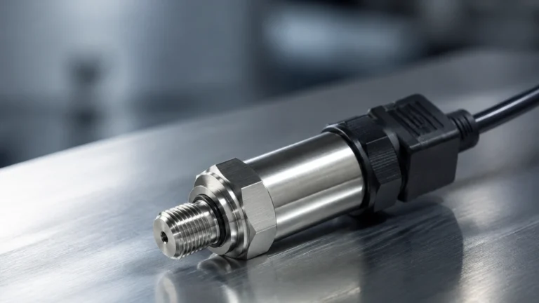
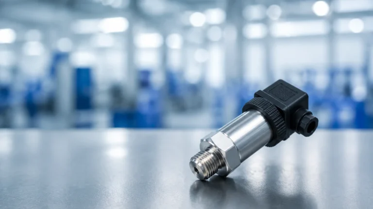
Hydrostatic transmitters measure the pressure exerted by the column of liquid and solids above the sensor. In a thickener, this is often used to determine "bed mass." By placing a pressure transmitter near the bottom of the tank, the thickener optimizer can calculate the total weight of the solids. This is a critical metric because volume (level) and mass do not always correlate if the density of the settling material changes.
Sonar and Submerged Interface Detection
Advanced sonar systems are often the heart of a thickener optimizer. These sensors are submerged or mounted at the surface and use low-frequency sound waves to penetrate the suspended solids. They can distinguish between the "rag layer" (suspended flocs) and the "compacted bed." This dual-level data allows the optimizer to adjust flocculant dosing in real-time.
Key Evaluation Criteria for Thickener Instrumentation
Selecting the right tools for a thickener optimizer involves more than just picking a sensor; it requires matching the technology to the specific process slurry.
| Criterion | Radar (80GHz) | Ultrasonic | Hydrostatic | Sonar (Interface) |
| :— | :— | :— | :— | :— |
| Primary Target | Liquid Surface | Liquid Surface | Bed Mass/Density | Mud/Bed Interface |
| Accuracy | High (±2mm) | Moderate (±10mm) | High (Pressure) | Moderate |
| Steam/Dust Resistance | Excellent | Poor | N/A (Submerged) | N/A (Submerged) |
| Maintenance Requirement | Low | Moderate | Moderate (Cleaning) | High (Cleaning) |
| Installation Complexity | Low | Low | Moderate | High |
When evaluating these technologies, engineers must consider the "solids profile" of the thickener. A thickener optimizer is only as good as the weakest data point in its control loop. For instance, if the slurry is prone to heavy scaling, a non-contact radar may be superior to a submerged hydrostatic sensor.
Common Risks and Operational Limitations
Implementing a thickener optimizer is not without challenges. Several physical factors can interfere with accurate data collection:
1. Rake Interference: The rotating rake mechanism inside the thickener can cross the path of the sensor signal. This creates "ghost echoes" or false level readings. Modern sensors include software filters to mask out the rake, but improper placement can still lead to errors.
2. Foam and Scum: Heavy foam on the surface of the thickener can absorb ultrasonic pulses and scatter radar signals. In such cases, high-frequency 80GHz radar or stilling wells are necessary to maintain a stable signal.
3. Density Fluctuations: Hydrostatic sensors rely on a constant density to calculate level. In a thickener, the density is constantly changing. A thickener optimizer must use a combination of bed level (sonar) and bed mass (hydrostatic) to compensate for these changes.
4. Scaling and Buildup: In chemical or mining applications, calcium or other minerals can build up on submerged sensors. This scaling can insulate the sensor diaphragm or transducer, leading to drifted readings.

Installation Best Practices for Reliable Data
To ensure the thickener optimizer receives clean, actionable data, follow these engineering guidelines during installation:
* Sensor Placement: Mount sensors at a distance approximately 1/3 to 1/2 of the radius from the center well. This area typically provides the most representative measurement of the settling bed. Avoid mounting sensors directly over the feed well or too close to the outer wall where wall effects may occur.
* Stilling Wells: For radar and ultrasonic sensors, a stilling well (a vertical pipe) can help eliminate surface turbulence and foam. The pipe must have vent holes at the top to equalize pressure and should be made of a material resistant to the process fluid.
* Redundancy: In critical thickener operations, use redundant technologies. For example, combine a sonar interface sensor with a hydrostatic pressure transmitter. The thickener optimizer can then cross-reference the two signals to detect sensor failure or process upsets.
* Purging Systems: For submerged sensors like hydrostatic transmitters, implement a water or air purge system. This periodically flushes the sensor face to prevent the accumulation of solids and scale.
Frequently Asked Questions
Q: Can a thickener optimizer work with only one type of sensor?
A: While it is possible to run basic control with just a bed level sensor, a true thickener optimizer usually requires at least three data points: liquid level, bed level (interface), and underflow density/mass. This allows the system to manage both the settling rate and the compaction of the solids.
Q: How does flocculant dosing affect level measurement?
A: Flocculants change the settling rate and the clarity of the "interface." If the interface is too "fluffy" or poorly defined, some sonar or ultrasonic sensors may struggle to find a solid reflection. Choosing a sensor with adjustable sensitivity or frequency is vital in high-flocculant applications.
Q: What is the benefit of using 80GHz radar over 26GHz radar in thickeners?
A: 80GHz radar has a much narrower beam angle (typically 3 to 4 degrees). This makes it easier to avoid internal obstructions like the rake or support beams, and it provides a stronger reflection from the liquid surface through dust or light foam.
Conclusion
A thickener optimizer is an essential tool for modern industrial plants seeking to improve water recovery and mineral processing efficiency. However, the success of the optimization strategy depends entirely on the reliability of the underlying instrumentation. By understanding the measurement principles of radar, ultrasonic, and hydrostatic sensors, and by following strict installation protocols, operators can ensure their systems provide the accuracy needed for automated control. For those in the procurement or design phase, consulting the technical specifications on the Main Page of an experienced manufacturer will help in selecting the most cost-effective and durable solutions for specific industrial environments.