Sample Station
Sample Station
In industrial process control and environmental monitoring, a sample station serves as a dedicated point for the extraction and analysis of process fluids. Whether used in municipal water treatment, chemical processing, or oil and gas refining, the reliability of a sample station depends heavily on the precision of the instrumentation supporting it. Level measurement is a fundamental component of these stations, ensuring that sampling pumps do not run dry, vessels do not overflow, and the volume of the sample remains consistent for accurate analytical results.
Integrating level measurement into a sample station requires an understanding of both the fluid dynamics and the specific sensing technologies available. As a professional manufacturer of industrial level measurement instruments, Welk provides a range of solutions—including radar, ultrasonic, and hydrostatic sensors—designed to meet the rigorous demands of automated sampling environments. For technical specifications and product comparisons, engineers often consult the Main Page to review product options and application support.
Measurement Principles in Sample Station Instrumentation
Before selecting a sensor for a sample station, it is essential to understand the physical principles governing different measurement technologies. Each method offers distinct advantages depending on the fluid characteristics and the physical layout of the station.
Radar Level Measurement (Non-Contact)
Radar level meters operate on the principle of Time Domain Reflectometry (TDR) or Frequency Modulated Continuous Wave (FMCW). The device emits high-frequency electromagnetic pulses toward the liquid surface. When these pulses hit the medium, they are reflected back to the sensor. The instrument calculates the distance based on the time it takes for the signal to return.
In a sample station, radar is often preferred for volatile or corrosive chemicals. Because the signal is electromagnetic, it is unaffected by air temperature, pressure, or vacuum conditions. Radar sensors can accurately measure through vapor layers that might obstruct other technologies.
Ultrasonic Level Measurement
Ultrasonic sensors utilize sound waves rather than electromagnetic pulses. The transducer emits an ultrasonic pulse that travels through the air, reflects off the liquid surface, and returns to the sensor. The "time-of-flight" is used to determine the level.
Ultrasonic technology is highly cost-effective for water-based applications in open sample stations or sumps. However, because sound speed is influenced by air temperature and density, these sensors usually include integrated temperature compensation. They are less suitable for applications involving heavy foam or high-pressure vapors, which can absorb or distort the sound waves.
Hydrostatic Level Measurement
Hydrostatic transmitters measure the pressure exerted by a liquid column at a specific depth. The principle is based on the formula: $P = \rho \cdot g \cdot h$, where $P$ is pressure, $\rho$ is the density of the liquid, $g$ is gravity, and $h$ is the height of the liquid.
In a sample station, submersible hydrostatic sensors are frequently used in deep sumps or collection tanks. They provide a direct, continuous measurement that is unaffected by surface turbulence or foam. However, they require the liquid density to remain relatively constant for high accuracy.
Key Evaluation Criteria for Sample Station Design
Selecting the appropriate level measurement technology for a sample station involves evaluating several technical factors. Failure to account for these can lead to measurement drift or hardware failure.
Fluid Compatibility
The chemical composition of the sample is the primary consideration. For corrosive samples, non-contact methods like radar or ultrasonic are ideal as they prevent hardware degradation. If a contact-based method like a magnetic level gauge or hydrostatic transmitter is used, the wetted materials (e.g., 316L stainless steel, PTFE, or PVC) must be compatible with the process medium.
Surface Conditions
Sample stations often involve agitated liquids or fluids that produce foam. Radar is generally more resilient to surface agitation than ultrasonic sensors. If heavy foam is present, a hydrostatic transmitter or a guided wave radar (GWR) may be necessary, as these technologies are less affected by surface irregularities.
Environmental Factors
Temperature fluctuations and ambient pressure can impact sensor performance. In outdoor sample stations, solar heating can affect the air space above the liquid, potentially skewing ultrasonic readings if not properly compensated. Radar sensors are largely immune to these environmental changes.
Practical Selection Table
The following table provides a general guide for selecting level measurement technology based on typical sample station requirements.
| Technology | Best For | Limitations | Accuracy (Typical) |
| :— | :— | :— | :— |
| Radar (Non-Contact) | Corrosive chemicals, high temp, vapors | Higher initial cost | ±2 mm to ±5 mm |
| Ultrasonic | Water, wastewater, open sumps | Affected by foam, dust, and vapor | ±0.25% of range |
| Hydrostatic | Deep tanks, sumps, turbulent surfaces | Requires constant liquid density | ±0.1% to ±0.5% FS |
| Magnetic Gauge | Visual indication, high-pressure tanks | Contact-based, moving parts | ±5 mm to ±10 mm |
| Level Switch | Point level detection, overfill alarm | No continuous data | N/A (Discrete) |
Installation Considerations and Best Practices
Proper installation is as critical as sensor selection. Even the most advanced radar or ultrasonic meter will fail if the installation environment creates signal interference.
1. Dead Zone Management: Every non-contact sensor has a "dead zone" (or blocking distance) near the transducer face where measurements cannot be taken. For a sample station with a shallow tank, the sensor must be mounted high enough to ensure the maximum liquid level does not enter this zone.
2. Beam Angle and Obstructions: Ultrasonic and radar signals spread out in a cone. If the sensor is mounted too close to a wall or near an inflow pipe, the signal may reflect off these surfaces rather than the liquid. Engineers should calculate the beam diameter at the maximum distance to ensure a clear path.
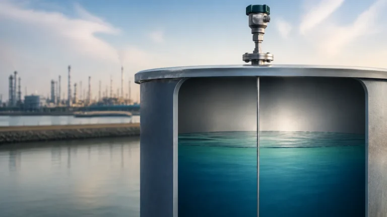
3. Stilling Wells: In applications with extreme turbulence or heavy foam, installing the sensor inside a stilling well (a vertical pipe) can provide a calm surface for measurement. This is particularly useful for radar and float-based systems.
4. Mounting Orientation: Sensors must be mounted perpendicular to the liquid surface. A tilt of even a few degrees can significantly reduce the strength of the reflected signal, leading to intermittent "loss of echo" errors.
Limitations and Common Risks
While modern instrumentation is highly reliable, there are inherent limitations to be aware of when designing a sample station.
* Vapor and Condensation: In closed sample vessels, condensation can form on the face of ultrasonic or radar transducers. While many Welk sensors feature drip-off designs or PTFE faces to mitigate this, heavy buildup can still cause signal attenuation.
* Build-up and Scaling: In wastewater sample stations, fats, oils, and grease (FOG) can accumulate on submerged sensors. Hydrostatic transmitters may require periodic cleaning of the diaphragm to prevent measurement lag.
* Power Supply Stability: Many sample stations are located in remote areas or at the "edge" of a plant's electrical grid. Fluctuations in power can cause electronic noise in 4-20mA loops. Using shielded cables and stabilized power supplies is mandatory for maintaining signal integrity.
Frequently Asked Questions (FAQ)
Q: Can I use an ultrasonic sensor for a chemical sample station?
A: Yes, provided the chemical does not produce heavy vapors or foam. For aggressive chemicals, ensure the sensor face is made of a resistant material like PVDF. If the chemical is highly volatile, radar is a safer choice.
Q: How often should I calibrate the level sensors in my sample station?
A: For most industrial applications, an annual calibration check is sufficient. However, if the sample station is used for regulatory compliance (e.g., environmental discharge monitoring), semi-annual or quarterly verification may be required.
Q: What is the advantage of using a level switch in addition to a continuous sensor?
A: A level switch provides a redundant safety layer. While a continuous sensor (like radar) provides data for process control, a high-level switch can trigger a hard-wired emergency stop to prevent overflows in the event of a controller or sensor failure.
Q: Are hydrostatic sensors affected by the size of the tank?
A: No. Hydrostatic pressure depends only on the height of the liquid and its density, not the total volume or the shape of the tank. This makes them highly versatile for irregularly shaped sample collection pits.
Conclusion
A well-engineered sample station is the backbone of process quality control. By selecting the correct level measurement technology—whether it be the precision of radar, the cost-effectiveness of ultrasonic, or the ruggedness of hydrostatic transmitters—operators can ensure continuous, accurate sampling. For those seeking to optimize their measurement systems, visiting the Main Page provides access to a wide array of industrial instruments and technical expertise tailored to complex automation needs. Proper attention to measurement principles, installation geometry, and fluid characteristics will result in a sample station that operates reliably with minimal maintenance overhead.