Sensor Def
Sensor Def
In the field of industrial automation and process control, the term "sensor def"—or sensor definition—refers to the fundamental characteristics, functional boundaries, and operational principles of devices designed to detect and measure physical phenomena. For level measurement, a sensor is essentially a transducer that converts the physical height or volume of a liquid or solid within a vessel into a standardized electrical signal (such as 4-20mA, HART, or RS485). Understanding the technical definition of these sensors is critical for engineers and procurement professionals to ensure system reliability and process safety.
Welk, as a professional manufacturer of industrial level measurement instruments, provides a wide array of technologies including radar, ultrasonic, and hydrostatic transmitters. Selecting the correct sensor requires a deep dive into the physics of the measurement and the specific constraints of the application environment. This guide serves as a practical engineering reference for defining and selecting the appropriate level sensor technology.
Core Measurement Principles
Before selecting a device, it is essential to define how different sensors interact with the medium. Level measurement technologies are generally categorized into non-contact and contact methods.
Radar Level Measurement (ToF)
Radar sensors utilize Time of Flight (ToF) technology. The sensor emits high-frequency microwave pulses (typically in the 26GHz or 80GHz range). These pulses travel at the speed of light, hit the surface of the medium, and reflect back to the sensor. The "sensor def" in this context relies on the dielectric constant (εr) of the material. A higher dielectric constant reflects more energy, providing a stronger signal. Radar is highly valued because it is independent of vacuum, pressure, and temperature fluctuations.
Ultrasonic Level Measurement
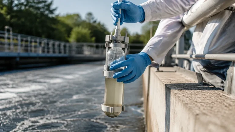
Similar to radar, ultrasonic sensors use ToF but rely on sound waves rather than electromagnetic waves. The sensor emits an ultrasonic pulse that travels through the air gap, reflects off the surface, and returns. Because sound speed is affected by air temperature, these sensors usually include an integrated temperature probe to compensate for variations. They are cost-effective for open-channel flow and water treatment but are limited in high-pressure or vacuum environments where sound cannot propagate effectively.
Hydrostatic Pressure Measurement
The definition of a hydrostatic sensor is based on Pascal’s Law, which states that the pressure at a specific point in a static fluid is proportional to the height of the fluid column above it. The formula used is $P = \rho \cdot g \cdot h$, where $P$ is pressure, $\rho$ is density, $g$ is gravity, and $h$ is height. These sensors are submerged or mounted at the bottom of a tank, measuring the weight of the liquid to determine the level.
Magnetic Level Gauges and Switches
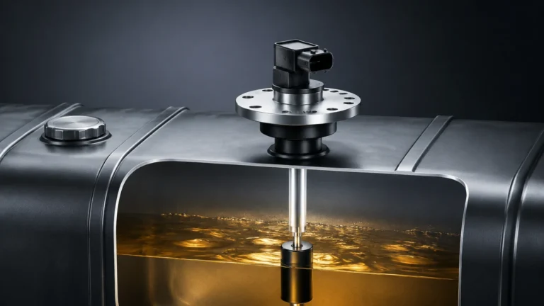
For point-level detection or visual bypass indication, magnetic sensors use a float containing a permanent magnet. As the liquid level rises, the float moves, activating dry reed switches or moving magnetic flaps. This provides a mechanical and electrical definition of the level that is highly reliable for high-pressure boilers and chemical storage.
Key Evaluation Criteria for Sensor Selection
Defining the right sensor for a project involves more than just picking a technology; it requires evaluating the interaction between the sensor and the process. Professionals should consult the Main Page of technical manufacturers to review specific model capabilities against these criteria.
1. Medium Properties: Is the liquid corrosive, viscous, or prone to foaming? For example, foam can absorb ultrasonic waves but may be penetrated or reflected differently by radar.
2. Process Conditions: Standard sensors operate at temperatures up to 80°C, but specialized radar units can handle over 250°C and pressures exceeding 40 bar (4.0 MPa).
3. Accuracy and Precision: In custody transfer, an accuracy of ±1mm is often required, making high-frequency radar the preferred choice. For general sump monitoring, ±10mm or 0.25% of the span may be sufficient.
4. Vessel Geometry: Internal obstructions like agitators, heating coils, or ladders can create "false echoes." Advanced sensors allow for "false echo suppression" to map out these fixed reflections.
Practical Selection Table
The following table provides a comparative overview to assist in the initial sensor definition phase for various industrial applications.
| Technology | Typical Accuracy | Max Range | Media Suitability | Key Advantage |
| :— | :— | :— | :— | :— |
| 80GHz Radar | ±1 mm | 120 m | Liquids, Solids, Corrosives | Narrow beam, ignores obstructions |
| Ultrasonic | ±0.25% FS | 15 – 30 m | Water, Wastewater | Non-contact, cost-effective |
| Hydrostatic | ±0.1% – 0.5% | 200 m H2O | Clean liquids, Oils | Simple installation, deep wells |
| Magnetic Gauge | ±5 mm – 10 mm | 6 m (Modular) | High pressure/temp chemicals | Visual and electrical output |
| Level Switch | N/A (Point) | N/A | Overfill protection | High reliability, safety SIL |
Installation Considerations and Best Practices
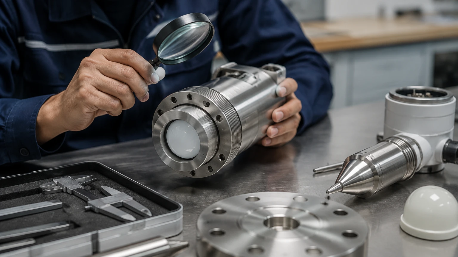
A sensor's performance is heavily dependent on its physical installation. Even the highest-spec sensor will fail if the "sensor def" parameters regarding placement are ignored.
* Dead Zones (Blocking Distance): Every non-contact sensor has a minimum distance (dead zone) near the face of the transducer where it cannot measure. For ultrasonic sensors, this might be 0.25m to 0.5m. The sensor must be mounted high enough so the maximum liquid level never enters this zone.
* Nozzle Dimensions: For radar and ultrasonic units, the mounting nozzle should be as short and wide as possible. If the nozzle is too long or narrow, the signal may reflect off the nozzle walls before reaching the medium.
* Positioning: Sensors should generally not be mounted in the center of a tank (to avoid multiple reflections from the tank walls) or near the fill inlet (to avoid interference from falling material).
* Submersible Venting: For hydrostatic sensors, the cable usually contains a vent tube to compensate for atmospheric pressure changes. This tube must be kept clear of moisture to prevent measurement drift.
Limitations and Common Risks
While modern instrumentation is robust, certain environmental factors can challenge the standard sensor definition:
* Heavy Steam and Condensation: In closed tanks with high-temperature liquids, condensation can form on the sensor face. While radar is largely unaffected, ultrasonic signals can be significantly attenuated.
* Dust and Solids: Measuring the level of grain, cement, or fly ash requires sensors with high sensitivity and dust-penetration capabilities. 80GHz radar is currently the industry standard for these applications due to its ability to process weak reflections from uneven surfaces.
* Vacuum Conditions: Ultrasonic sensors cannot function in a vacuum because sound waves require a medium (air/gas) to travel. Hydrostatic and radar sensors are the appropriate alternatives here.
* Density Fluctuations: Hydrostatic sensors assume a constant density. If the temperature of the liquid changes significantly or if different liquids are mixed, the density changes, leading to errors in level calculation unless compensation is applied.
Frequently Asked Questions (FAQ)
Q: What is the difference between a level transmitter and a level switch?
A: A level transmitter provides continuous measurement (e.g., 0% to 100% full), whereas a level switch provides point-level detection (e.g., a signal only when the tank is 90% full) to prevent overfills or dry running.
Q: How does the dielectric constant affect radar sensors?
A: The dielectric constant (εr) is a measure of a material's ability to store electrical energy. Materials with low εr (like oils or liquefied gases) reflect less radar energy, requiring more sensitive electronics or guided wave radar (GWR) technology.
Q: Can I use an ultrasonic sensor for acids?
A: Yes, provided the sensor face is made of a chemically resistant material such as PVDF or PTFE. However, if the acid produces heavy vapors, radar may be more reliable.
Q: How often should level sensors be calibrated?
A: This depends on the industry and the technology. Hydrostatic sensors may drift over time and require annual calibration. Radar sensors, being digital and non-contact, often maintain accuracy for several years without physical recalibration, though periodic verification is recommended.
Conclusion
Defining the requirements for a level sensor involves a comprehensive understanding of the process medium, the physical environment, and the limitations of each measurement principle. By establishing a clear "sensor def" at the beginning of a project, engineers can avoid costly downtime and maintenance issues. For those seeking specific product specifications and engineering support, visiting the Main Page of an established manufacturer like Welk is the recommended next step to ensure the selected hardware aligns with the theoretical requirements of the application.