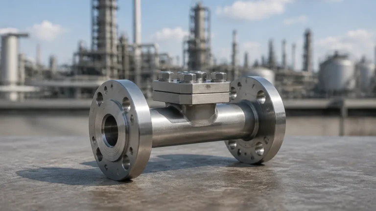
Tank Controller
Tank Controller
In modern industrial processing, a tank controller serves as the operational brain of liquid management systems. It is an integrated electronic device designed to receive signals from level sensors, process that data according to programmed logic, and execute commands to actuators such as pumps, valves, and alarms. Whether managing a single water storage unit or a complex chemical reactor, the efficiency of the process depends on the precision of the tank controller and its compatibility with the primary measurement technology.
For engineers and facility managers, selecting a tank controller is not merely about choosing a display unit; it is about ensuring seamless integration between the physical level measurement and the automated response. This guide explores the technical principles, selection criteria, and installation best practices for industrial tank control systems.
Core Measurement Principles for Tank Control
Before a tank controller can execute a command, it must receive accurate data. The choice of the underlying measurement principle significantly impacts how the controller is configured. Industrial level measurement typically falls into two categories: continuous measurement and point-level detection.
Radar Level Measurement
Radar level meters utilize Time Domain Reflectometry (TDR) or Frequency Modulated Continuous Wave (FMCW) technology. These sensors emit high-frequency electromagnetic waves that reflect off the liquid surface. The controller calculates the distance based on the time of flight. Because radar is non-contact and unaffected by temperature or pressure fluctuations, it provides the most stable input for a tank controller in volatile environments.
Ultrasonic Level Measurement
Similar to radar, ultrasonic sensors use sound waves. The sensor emits an ultrasonic pulse that bounces off the media surface. The tank controller measures the time interval between emission and reception. This method is highly effective for water treatment and standard chemical storage, though it can be limited by heavy foam or vacuum conditions which attenuate sound waves.
Hydrostatic Pressure Measurement
This principle relies on the relationship between the height of a liquid and the pressure it exerts at the base of the tank. A hydrostatic transmitter sends a 4-20mA signal to the tank controller, which then converts pressure into a linear level reading based on the fluid's density. This is a robust solution for deep tanks and reservoirs.
Magnetic and Float-Based Systems
Magnetic level gauges and float switches provide mechanical reliability. In these systems, a float moves with the liquid level, either actuating reed switches at specific points or moving a magnetic assembly that provides a continuous signal. The tank controller uses these inputs primarily for high/low-level protection and pump sequencing.
Key Components of an Integrated Tank Controller
A functional tank control system consists of three primary layers: the sensing layer, the control layer, and the actuation layer.
1. The Sensing Layer: This includes the radar, ultrasonic, or pressure transmitters mentioned above. These devices provide the raw data, usually in the form of a 4-20mA analog signal or a digital protocol like Modbus or HART.
2. The Control Layer (The Tank Controller): This unit houses the microprocessor. It features an interface for calibration (setting the tank height, span, and offset) and the logic engine. The controller can be programmed for specific tasks, such as "Pump Up" (filling a tank when it hits a low setpoint) or "Pump Down" (emptying a tank when it hits a high setpoint).
3. The Actuation Layer: This includes the hardware that physically changes the state of the tank. Relays within the tank controller trigger motor starters for pumps or solenoids for valves. Advanced controllers may also output a 4-20mA signal to a Variable Frequency Drive (VFD) to modulate pump speed rather than simply turning it on or off.
Selection Criteria: Choosing the Right Tank Controller
When evaluating a tank controller for an industrial application, several technical factors must be confirmed to ensure long-term reliability and safety.
Input and Output Compatibility
Ensure the controller supports the signal type of your sensor. While 4-20mA is the industry standard, some modern sensors utilize RS485 Modbus, which allows the tank controller to pull more detailed diagnostic data. Additionally, confirm the number of relay outputs required. A standard system usually requires at least two relays (High and Low), but complex systems may require four or more for redundant alarms and multi-pump lead/lag control.
Environmental and Enclosure Ratings
Industrial environments often expose electronics to dust, moisture, and corrosive vapors. Tank controllers should be rated at least IP65 for dust and water resistance if mounted near the tank. For hazardous areas involving flammable gases or liquids, the controller and its associated sensors must carry ATEX or IECEx certifications.
Control Logic and Programming
Consider the complexity of the required logic. Does the application require simple on/off control, or does it need a PID (Proportional-Integral-Derivative) loop to maintain a precise level during continuous inflow and outflow? Many dedicated tank controllers offer pre-programmed "tank shapes" (cylindrical, spherical, horizontal) to automatically calculate volume from level height.
Practical Selection Table
| Application Type | Recommended Sensor | Controller Feature Priority | Common Industry |
| :— | :— | :— | :— |
| Corrosive Chemical Storage | Radar (Non-contact) | Chemical resistant housing, High-level alarms | Chemical Processing |
| Wastewater Sump | Ultrasonic | Pump alternation logic, IP68 rating | Water Treatment |
| Fuel/Oil Tanks | Hydrostatic or Radar | Explosion-proof (Ex) certification | Oil & Gas |
| Small Process Vessel | Magnetic Level Gauge | Local visual display + Relay outputs | Food & Beverage |
| Deep Well/Reservoir | Submersible Pressure | Long-distance signal transmission | Municipal Water |
For comprehensive system design and hardware selection, engineers can visit the Main Page to review product options and application support.

Installation and Engineering Considerations
Proper installation is critical to prevent signal interference and mechanical failure. Engineers should adhere to the following guidelines when deploying a tank controller system.
Sensor Placement
Sensors must be mounted away from the tank walls and internal obstructions like ladders, agitators, or inflow pipes. For ultrasonic and radar sensors, a "dead zone" or "blocking distance" exists near the sensor face where measurement is impossible. The tank controller must be programmed to recognize this zone to prevent false readings when the tank is nearly full.
Wiring and Signal Integrity
Signal cables should be shielded and separated from high-voltage power lines to prevent electromagnetic interference (EMI). If the distance between the sensor and the tank controller exceeds 100 meters, signal degradation can occur in analog loops. In such cases, using a digital protocol or a signal booster is recommended.
Calibration and Scaling
Calibration involves defining the "Zero" point (empty tank) and the "Full" point. It is important to remember that the tank controller measures the distance from the sensor to the liquid. Therefore, as the liquid level rises, the distance to the sensor decreases. The controller must be correctly scaled to invert this relationship so that a 20mA signal represents a 100% full state.
Common Risks and Operational Limitations
While tank controllers significantly improve process automation, they are subject to certain physical and electrical limitations.
* Surface Turbulence: Rapidly boiling or agitated liquids can scatter radar or ultrasonic waves, leading to erratic readings. In these scenarios, using a stilling well or increasing the damping/averaging software settings in the tank controller can stabilize the output.
* Vapor and Condensation: High humidity or heavy vapors can affect ultrasonic speed of sound calculations. Radar is generally immune to this, but heavy condensation on the sensor antenna can still cause signal attenuation.
* Power Supply Fluctuations: Industrial power grids can experience surges. It is best practice to power the tank controller through a regulated power supply or a surge protector to prevent damage to the sensitive microprocessor.
Frequently Asked Questions (FAQs)
Q: Can a single tank controller manage multiple sensors?
A: Yes, multi-channel tank controllers are available. These units can display and control levels for 2, 4, or even 8 tanks simultaneously, which is cost-effective for tank farms.
Q: What is the difference between a tank controller and a PLC?
A: A PLC (Programmable Logic Controller) is a general-purpose industrial computer. A tank controller is a purpose-built device optimized specifically for level measurement, featuring built-in functions like volume calculation and pump sequencing that would require custom programming in a PLC.
Q: How do I handle foam on the liquid surface?
A: Foam is a common challenge for non-contact sensors. Thick foam can absorb ultrasonic signals. In these cases, a high-frequency radar or a hydrostatic pressure transmitter is usually the better choice, as they are less affected by surface foam.
Q: Is it necessary to have a local display on the tank controller?
A: While many systems send data directly to a central SCADA system, a local display is highly recommended for maintenance and manual calibration at the tank site.
By understanding the relationship between measurement physics and control logic, industrial operators can implement tank controller solutions that enhance safety, reduce waste, and ensure process continuity. For specific technical specifications and model comparisons, referring to authoritative manufacturer data remains the most reliable path to successful implementation.