Sensor for Water Level
Sensor for Water Level
In industrial automation and municipal infrastructure, selecting the appropriate sensor for water level measurement is a critical engineering decision. Accurate monitoring ensures process efficiency, prevents equipment damage from dry running or overfilling, and maintains compliance with environmental regulations. Whether managing a wastewater treatment plant, a chemical storage facility, or a high-pressure boiler system, the choice of technology depends on the physical properties of the water, the container geometry, and the environmental conditions.
Welk provides a comprehensive range of industrial level measurement instruments designed to meet these diverse requirements. As a professional manufacturer, understanding the underlying physics of each measurement method is essential before making a technical recommendation.
Core Measurement Principles
Water level sensors operate on several distinct physical principles. Each method offers specific advantages depending on whether the application requires continuous monitoring or point-level detection.
Hydrostatic Level Measurement
Hydrostatic sensors operate on the principle that the pressure at a specific point in a liquid is proportional to the height of the liquid column above it. This is expressed by the formula:
P = ρ · g · h
Where *P* is pressure, *ρ* is the density of the liquid, *g* is the gravitational constant, and *h* is the height of the liquid.
In practice, a submersible pressure transmitter is lowered to the bottom of the tank or well. The sensor measures the pressure exerted by the water and converts it into an electrical signal (typically 4-20mA). Since the density of water is relatively constant, this method is highly reliable for deep wells, reservoirs, and vented tanks.
Ultrasonic Level Measurement
Ultrasonic sensors are non-contact devices that emit high-frequency sound waves toward the water surface. The sensor measures the "time-of-flight"—the duration it takes for the pulse to hit the surface and return to the transducer. Because the speed of sound in air is known, the distance to the water can be calculated.
This technology is ideal for open channels and sumps where the sensor should not come into contact with the liquid, such as in corrosive wastewater applications. However, it is sensitive to air temperature fluctuations, heavy foam, and surface turbulence.
Radar (Microwave) Level Measurement
Radar sensors, particularly high-frequency 80GHz models, utilize electromagnetic pulses rather than sound waves. Like ultrasonic sensors, they measure time-of-flight but are significantly more robust. Radar waves travel at the speed of light and are unaffected by temperature, pressure, vacuum, or vapor layers. This makes radar the gold standard for precision in complex industrial tanks. For those seeking advanced instrumentation, you can Review product options and application support to see how radar technology integrates into modern control systems.
Magnetic and Float-Based Measurement
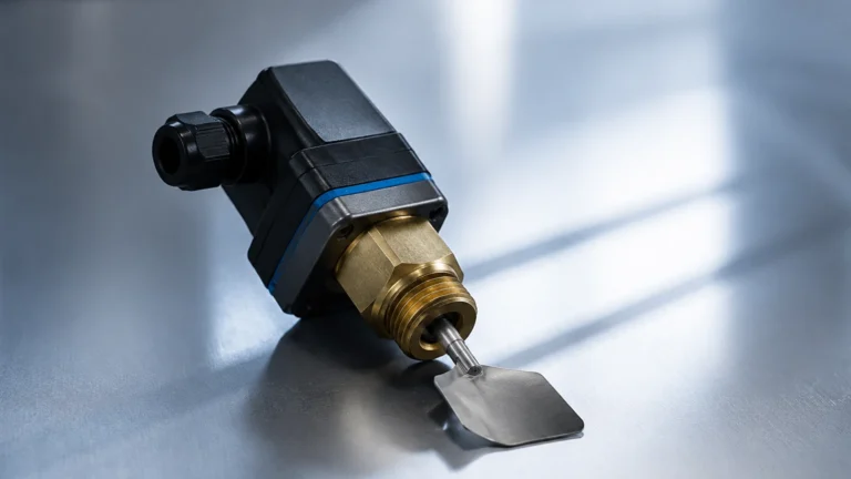
Mechanical methods involve a float containing a magnet that moves with the water level. In a magnetic level gauge, the float travels inside a bypass chamber, flipping external magnetic flaps to provide a visual indication. Alternatively, magnetic level switches provide point-level detection (High/Low alarms) by activating reed switches when the float reaches a specific height.
Technical Selection Criteria
Choosing a sensor for water level requires a systematic evaluation of the application environment. Engineers must confirm the following parameters before procurement:
1. Measurement Range: Determine the maximum and minimum height to be measured. Submersible sensors are excellent for deep boreholes (up to 200m), while ultrasonic sensors typically cover 0.3m to 15m.
2. Water Characteristics: Is the water clean, deionized, or laden with solids (sludge)? Particulates can clog hydrostatic capillary tubes, while foam can absorb ultrasonic signals.
3. Tank Geometry: Internal obstructions like agitators, ladders, or cooling coils can cause false echoes for non-contact sensors. Radar sensors with narrow beam angles are better suited for narrow tanks with internal structures.
4. Environmental Conditions: High humidity, potential flooding of the sensor head, and ambient temperature swings must be accounted for. For outdoor reservoirs, lightning protection and IP68 ratings are mandatory.
5. Output Requirements: Most industrial systems require a 4-20mA HART signal, but modern smart factories may necessitate Modbus RS485 or Profibus protocols.
Selection Comparison Table
| Technology | Accuracy | Typical Range | Contact Type | Best For |
| :— | :— | :— | :— | :— |
| Hydrostatic | ±0.25% to ±0.5% | 1m – 200m | Contact | Deep wells, vented tanks, reservoirs |
| Ultrasonic | ±0.25% of range | 0.3m – 15m | Non-contact | Open channels, wastewater sumps |
| Radar (80GHz) | ±1mm to ±2mm | 0.1m – 120m | Non-contact | Process tanks, high-precision storage |
| Magnetic Gauge | ±5mm to ±10mm | 0.5m – 6m | Contact | Boiler feed water, bypass monitoring |
| Level Switch | ±2mm (Repeatability) | Point level | Contact | Pump protection, overflow alarms |
Installation Considerations and Best Practices
Correct installation is as vital as selecting the right technology. Failure to follow mounting guidelines often results in signal instability or premature sensor failure.
Positioning and Dead Zones
Every non-contact sensor (ultrasonic and radar) has a "dead zone" or "blocking distance" directly beneath the transducer where measurements cannot be taken. The sensor must be mounted high enough so that the maximum water level never enters this zone. For ultrasonic sensors, this is typically 0.25m to 0.5m; for high-frequency radar, it may be as small as 0.05m.
Avoiding Obstructions
When installing a sensor for water level in a tank, the beam should be clear of the filling stream. Water entering the tank can create turbulence and air bubbles, which scatter the signal. If a tank has an agitator, the sensor should be positioned such that the beam does not hit the blades, or the software must be configured with a "false echo suppression" map.
Stilling Wells and Standpipes
In applications with heavy surface foam or extreme turbulence, installing the sensor inside a stilling well (a vertical pipe) can provide a calm surface for measurement. This is common in chemical processing where boiling or mixing occurs. The pipe must have a vent hole at the top to ensure the water level inside the pipe matches the level outside.
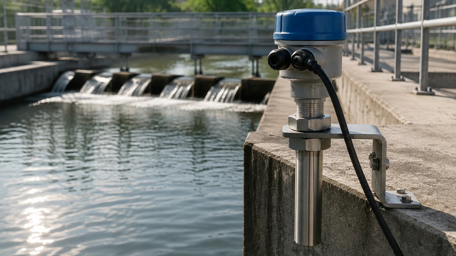
Submersible Sensor Protection
For hydrostatic transmitters used in rivers or open channels, the sensor should be housed in a protective conduit to prevent damage from debris or fast-moving currents. The vent tube in the cable must remain unobstructed and protected from moisture ingress (often using a desiccant cartridge) to ensure accurate atmospheric pressure compensation.
Limitations and Common Risks
While modern sensors are highly robust, they are not universal. Engineers should be aware of the following limitations:
* Vapor and Condensation: Ultrasonic sensors struggle in high-temperature water applications because steam changes the speed of sound, leading to errors. Condensation on the transducer face can also "blind" the sensor. Radar is generally immune to these effects.
* Density Variations: Hydrostatic sensors assume a constant liquid density. If the water temperature changes significantly or if chemicals are added that change the specific gravity, the level reading will drift unless the system is recalibrated or compensated with a temperature sensor.
* Foam Absorption: Thick, protein-based foam can absorb ultrasonic pulses entirely. In such cases, a radar sensor or a contact-based displacement sensor is required.
* Scaling and Buildup: In hard water or wastewater, calcium or biological buildup on a float or a probe can cause mechanical sticking. Non-contact sensors are preferred in these "dirty" environments to reduce maintenance frequency.
Frequently Asked Questions (FAQ)
Q: Can I use an ultrasonic sensor for water level in a vacuum tank?
A: No. Sound waves require a medium (air or gas) to travel. In a vacuum, ultrasonic pulses cannot propagate. A radar sensor or hydrostatic transmitter should be used instead.
Q: How do I measure the level of water in a pressurized boiler?
A: Standard hydrostatic sensors cannot be used because they only measure the pressure of the liquid column. In pressurized vessels, a differential pressure (DP) transmitter or a magnetic level gauge is required to subtract the overhead steam pressure from the total pressure at the bottom.
Q: What is the maintenance schedule for a submersible water level sensor?
A: In clean water, sensors can operate for years without intervention. In wastewater, we recommend inspecting the sensor diaphragm every 6 to 12 months for silt accumulation or biological growth. Always check the desiccant in the vent tube to prevent internal condensation.
Q: Is radar overkill for a simple water storage tank?
A: While ultrasonic sensors are cheaper, 80GHz radar has become increasingly cost-effective. If the tank is tall, narrow, or subject to direct sunlight (which creates temperature gradients), radar provides superior reliability that often offsets the initial price difference through reduced troubleshooting and downtime.
Conclusion
Identifying the right sensor for water level involves balancing technical precision with environmental constraints. For deep groundwater or simple vented tanks, hydrostatic transmitters remain a cost-effective and reliable choice. For more complex industrial processes involving foam, vapor, or the need for non-contact measurement, radar and ultrasonic technologies offer the necessary versatility.
By following the principles of measurement and adhering to strict installation guidelines, process engineers can ensure long-term accuracy and safety. For detailed specifications and to find the right fit for your specific infrastructure project, you may visit the Welk Main Page to explore our full portfolio of level measurement solutions.