Silo Ingredients
Silo Ingredients
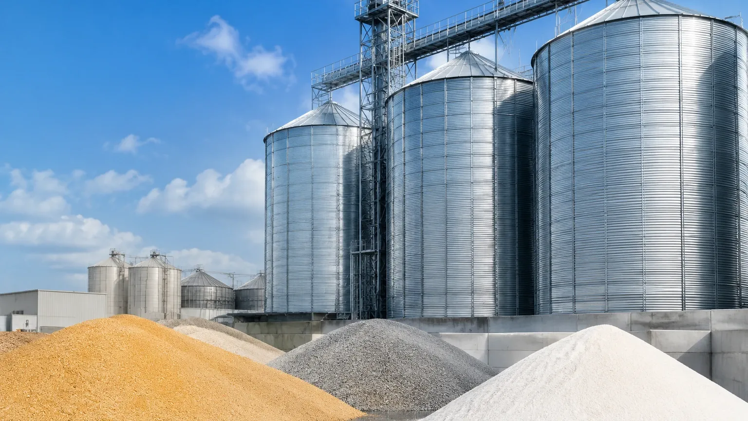
In industrial processing and storage, the term "silo ingredients" encompasses a vast array of raw materials, ranging from fine powders like flour and cement to granular solids such as plastic pellets, grains, and minerals. Efficiently managing these ingredients is a cornerstone of supply chain reliability and process safety. However, the physical characteristics of these materials—such as dust generation, varying moisture levels, and the formation of steep angles of repose—present significant challenges for accurate level measurement.
Accurate inventory management of silo ingredients prevents costly production halts due to material shortages and eliminates the risks associated with overfilling. To achieve this, engineers must select level measurement technologies based on the specific physical and chemical properties of the stored media. This article explores the principles of level measurement for silo-stored materials, provides selection criteria, and outlines installation best practices.
Principles of Level Measurement for Silo Ingredients
Measuring the level of solids in a silo is fundamentally different from measuring liquids. Solids do not maintain a flat surface; they form cones during filling and craters during discharge. Furthermore, the environment inside a silo containing dry ingredients is often characterized by heavy dust and high pressure. The following technologies are the most prevalent in modern industrial applications.
Non-Contact Radar (FMCW)
Non-contact radar, particularly Frequency Modulated Continuous Wave (FMCW) radar, is widely considered the gold standard for monitoring silo ingredients. These devices emit high-frequency microwave signals (typically 26 GHz or 80 GHz). The signal reflects off the material surface and returns to the sensor. The time difference or frequency shift is used to calculate the distance.
* 80 GHz Radar: This high frequency allows for a very narrow beam angle (often as small as 3 degrees). A narrow beam is essential for silos with internal obstructions like ladders or reinforcement struts, as it avoids false reflections. It also performs exceptionally well in penetrating heavy dust clouds generated during pneumatic filling.
* 26 GHz Radar: Often used for larger granules or where the signal needs to cover a wider area, though it is more susceptible to interference from silo walls in narrow vessels.
Guided Wave Radar (TDR)
Guided Wave Radar (GWR) uses Time Domain Reflectometry (TDR). A probe (cable or rod) extends the full height of the silo, and the microwave pulse travels along this lead. When the pulse hits the silo ingredients, a portion is reflected due to the change in dielectric constant.
This method is highly effective for materials with low dielectric constants (εr) because the probe concentrates the energy. However, silo ingredients that are heavy or abrasive can exert significant tensile pull on the cable, potentially damaging the sensor or the silo roof. GWR is often preferred in smaller silos or bypass pipes.
Ultrasonic Level Sensors
Ultrasonic sensors emit sound waves that bounce off the material surface. They are cost-effective and easy to install. However, their application for silo ingredients is limited. Sound waves are easily absorbed by soft powders and can be scattered by the uneven surfaces of granular solids. Furthermore, heavy dust can attenuate the signal, leading to "lost echo" errors. They are best suited for large-grain solids in low-dust environments.
Mechanical Systems (Plumb Bob and Rotary Switches)
* Plumb Bob: A weighted sensor is lowered on a cable at timed intervals. When it touches the material, the tension change is detected, and the distance is recorded. While mechanical, it is highly reliable for very tall silos where electronic signals might struggle.
* Rotary Paddle Switches: These are point-level sensors used to detect high or low states. A small motor rotates a paddle; when silo ingredients reach the paddle, the rotation is impeded, triggering a switch. These are essential for overfill prevention.
Evaluating Silo Ingredients for Sensor Selection
Before selecting a measurement device, the specific characteristics of the silo ingredients must be documented. The following factors are critical:
1. Dielectric Constant (εr): This determines how much signal a radar sensor can reflect. Materials like plastic pellets have low εr (approx. 1.5–2.0), requiring more sensitive electronics or guided wave radar. Minerals and metallic ores have high εr, making them easier to detect.
2. Bulk Density: Heavier materials exert more force on contact probes. If using Guided Wave Radar, the tensile load must be calculated to ensure the silo roof can support the weight of the material pulling on the cable.
3. Particle Size and Shape: Fine powders (e.g., fly ash) create significant dust, necessitating high-frequency radar. Large, irregular chunks (e.g., crushed stone) can cause signal scattering.
4. Moisture Content: Increased moisture increases the dielectric constant but can also lead to material "clumping" or buildup on the sensor face.
Selection Table for Common Silo Ingredients
| Ingredient Type | Example Materials | Recommended Technology | Primary Challenge |
| :— | :— | :— | :— |
| Fine Powders | Cement, Flour, Lime | 80 GHz Non-contact Radar | Heavy dust, signal attenuation |
| Granular Solids | Plastic Pellets, Rice | Guided Wave Radar or Radar | Low dielectric constant |
| Large Aggregates | Coal, Gravel, Ore | 80 GHz Radar or Plumb Bob | Surface irregularities, impact |
| Lightweight Solids | Sawdust, Perlite | 80 GHz Radar | Very low reflection, high dust |
| Corrosive/Chemical | Fertilizer, Salt | PTFE-coated Radar | Chemical attack, crusting |
For more detailed technical specifications and product comparisons, you can review product options and application support on our Main Page.
Installation Considerations and Best Practices
Correct installation is as important as selecting the right technology. Even the most advanced sensor will fail if placed incorrectly.
Positioning and the Angle of Repose
Silo ingredients do not sit flat. When filling from the center, a cone forms (angle of repose). When discharging, a funnel or "rat-hole" may form. Sensors should typically be mounted at 1/6th to 1/3rd of the silo diameter from the wall. This position provides a representative average of the material level, minimizing the error caused by the peak or valley of the material cone.
Avoiding the Fill Stream
Never install a level sensor directly in the path of the incoming material. The falling silo ingredients will cause massive interference for radar and ultrasonic signals and can physically damage mechanical probes or cables.
Aiming Flanges (Swivel Mounts)
For solids, the signal often reflects away from the sensor because of the sloped surface. Using an adjustable aiming flange allows the technician to tilt the radar sensor toward the center of the material cone, maximizing the reflected signal strength (echo return).
Nozzle Geometry
The mounting nozzle should be as short as possible. If the nozzle is too long and narrow, the radar signal may reflect off the internal edges of the nozzle before it even enters the silo, creating a "near-zone" interference that masks the actual material level.
Limitations and Common Risks
* Material Buildup: In silos containing flour or moist ingredients, material can cake onto the sensor antenna. While many modern radars can "see through" a thin layer of buildup, excessive accumulation will eventually cause signal loss. Air purging systems are often used to keep the antenna clean.
* Static Electricity: The movement of dry silo ingredients, especially plastics and grains, can generate significant static charges. Sensors must be properly grounded to prevent electronic failure or, in the case of combustible dusts, to prevent them from becoming an ignition source.
* Internal Obstructions: Cross-braces, ladders, and agitators are common in industrial silos. These create false echoes. Advanced software mapping (False Signal Suppression) is required to "teach" the sensor to ignore these fixed objects.
Frequently Asked Questions (FAQ)
Q: Can I use the same sensor for cement and plastic pellets?
A: While an 80 GHz radar can measure both, the settings will differ. Plastic pellets have a much lower dielectric constant, meaning the sensor needs to be more sensitive to detect the weaker reflection compared to the stronger reflection from cement.
Q: How do I handle measurement during pneumatic filling?
A: Pneumatic filling creates extreme dust and turbulence. High-frequency 80 GHz radar is the most effective solution here, as shorter wavelengths penetrate dust more efficiently than ultrasonic or lower-frequency radar signals.
Q: Is Guided Wave Radar safe for tall silos?
A: It depends on the material. For heavy silo ingredients like sand or grain in a silo over 15 meters, the "pull-down" force on the cable can exceed several tons. In these cases, non-contact radar is safer for the structural integrity of the silo.
Q: What is the maximum range for these sensors?
A: Most industrial radar sensors can measure up to 30 meters, with specialized long-range versions reaching up to 120 meters (approx. 393 feet). Ultrasonic sensors are generally limited to 15–20 meters in solids.
Conclusion
Managing silo ingredients effectively requires a deep understanding of both the material properties and the physics of the measurement technology. While mechanical methods still have their place, the industry is moving toward high-frequency non-contact radar due to its reliability in dust and its lack of wear-and-tear. By carefully considering the dielectric constant, the silo geometry, and the potential for dust or buildup, engineers can implement a level measurement solution that ensures continuous, safe, and efficient production. For further assistance in selecting the correct instrument for your specific application, visit our Main Page for comprehensive technical resources.