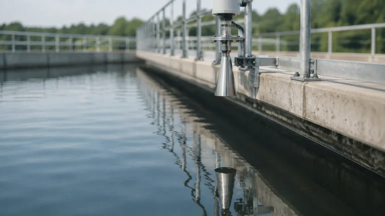
Silo Level Indicator
Silo Level Indicator
In industrial bulk solids management, the ability to accurately monitor inventory is essential for operational efficiency, safety, and supply chain reliability. A silo level indicator is not a single device but a category of instruments designed to detect the presence or volume of materials such as grains, cement, plastic pellets, or minerals stored in large vessels. Unlike liquid level measurement, solids present unique challenges, including uneven surfaces, heavy dust, and varying material densities.
Selecting the correct silo level indicator requires a deep understanding of the material's physical properties and the silo's mechanical environment. This guide explores the fundamental measurement principles, selection criteria, and installation best practices for modern silo level monitoring.
Measurement Principles for Silo Level Indicators
Level measurement in silos is generally divided into two categories: point level detection and continuous level measurement. Each relies on different physical principles to interact with the bulk material.
Point Level Detection (Switches)
Point level indicators are used to detect a specific level—typically high, mid, or low—to prevent overfills or ensure the silo does not run empty.
* Rotary Paddle Switches: This is a mechanical principle where a motor slowly rotates a paddle. When the material reaches the paddle, it creates resistance, stalling the motor and triggering an electrical switch. It is highly reliable for materials with a density greater than 100 g/l (6.2 lb/ft³).
* Vibrating Rod/Fork Sensors: These sensors use piezoelectric crystals to vibrate a rod or fork at its natural frequency. When the material covers the sensor, the vibration is dampened. The electronic circuit detects this change in frequency or amplitude and switches the output. These are ideal for fine powders and low-density materials.
* Capacitance Switches: These measure the change in electrical capacitance between the sensor probe and the silo wall. As material displaces air around the probe, the dielectric constant changes, triggering the alert.
Continuous Level Measurement (Transmitters)
Continuous transmitters provide real-time data on the exact level of material throughout the entire height of the silo.
* Radar Level Meters (Non-Contact): Modern radar indicators use Frequency Modulated Continuous Wave (FMCW) technology, typically operating at high frequencies like 80 GHz. The sensor emits a microwave signal that reflects off the material surface. The time-of-flight or frequency shift is used to calculate the distance. High-frequency radar is preferred for silos because it offers a narrow beam angle, allowing it to avoid internal obstructions like ladders or reinforcements.
* Ultrasonic Level Sensors: These emit an ultrasonic pulse that reflects off the material surface. While cost-effective, they are sensitive to air temperature changes and heavy dust, which can attenuate the sound wave. They are best suited for shorter silos (under 15 meters / 49 feet) with low-dust environments.
* Guided Wave Radar (GWR): This technology uses a cable or rod probe that extends to the bottom of the silo. The radar pulse travels along the probe, making it immune to dust and surface turbulence. However, the probe is subject to heavy mechanical pull forces as the material settles or is discharged.
Selection Criteria and Technology Comparison
Choosing a silo level indicator depends on the material's dielectric constant (εr), moisture content, and the presence of dust. For example, plastic pellets have a low dielectric constant, requiring high-sensitivity radar, while cement creates heavy dust that would blind an ultrasonic sensor.
Selection Table: Technology vs. Material Suitability
| Technology | Best For | Max Range (Typical) | Dust Resistance | Surface Profile Sensitivity |
| :— | :— | :— | :— | :— |
| 80 GHz Radar | Powders, Granules, Aggregates | 120 m (393 ft) | Excellent | Low |
| Ultrasonic | Pellets, Non-dusty solids | 30 m (98 ft) | Poor | High |
| Rotary Paddle | High-level alarm (Heavy solids) | N/A (Point) | Excellent | N/A |
| Vibrating Rod | Low-level alarm (Fine powders) | N/A (Point) | Excellent | N/A |
| Guided Wave Radar | Low dielectric materials | 75 m (246 ft) | Excellent | Low |
When evaluating options, engineers should consult technical documentation to ensure the instrument's pressure and temperature ratings match the process. For a comprehensive overview of industrial-grade sensors, you can visit the Main Page of our product catalog.
Installation and Positioning Strategy
The performance of a silo level indicator is often determined by its installation location. Unlike liquids, bulk solids form an "angle of repose," creating a cone-up shape during filling and a cone-down shape during discharge.
1. Avoiding the Fill Stream
Never install a level sensor directly in the path of the incoming material. This causes false readings and can physically damage the sensor or its probe. The sensor should be positioned away from the inlet but close enough to represent the average level.
2. The 1/6th or 1/3rd Rule
For silos with a center fill and center discharge, the most accurate "average" level is typically found at approximately 1/6th to 1/3rd of the silo's diameter from the outer wall. This placement minimizes the error caused by the angle of repose.
3. Nozzle Considerations
For radar and ultrasonic sensors, the mounting nozzle should be as short as possible. If the nozzle is too long or narrow, the signal may reflect off the nozzle's internal edges, creating a "dead zone" or "ringing" effect that obscures the actual material level.
4. Aiming Flanges (Gimbals)
Because solid surfaces are rarely flat, many radar silo level indicators are equipped with adjustable aiming flanges. This allows the technician to tilt the sensor so the beam is perpendicular to the material's slope, maximizing the returned signal strength.
Managing Challenges in Bulk Solids
Industrial silos present several environmental risks that can interfere with level measurement accuracy:
* Dust and Vapor: In industries like cement or flour milling, dust clouds can be extremely dense. Non-contact radar is the gold standard here because microwaves are not significantly affected by air density or suspended particles.
* Material Buildup: Sticky materials can accumulate on the sensor face. While many modern radar units feature a flat-face antenna design that resists buildup, some applications may require an integrated air purge system to blow away dust and maintain signal clarity.
* Mechanical Pull Forces: In tall silos, the downward movement of material can exert several tons of force on the cables of guided wave radar or weight-and-cable systems. It is critical to confirm the tensile strength of the cable and the structural integrity of the silo roof before installation.
* Internal Obstructions: Cross-braces, ladders, and agitators can create "false echoes." Advanced software in modern transmitters allows for "echo mapping," where the sensor is taught to ignore static reflections from these fixed objects.
Maintenance and Operational Best Practices
While many modern silo level indicators are designed to be maintenance-free, a regular inspection schedule ensures long-term reliability.
1. Visual Inspection: Periodically check the sensor face or paddle for signs of wear, corrosion, or excessive material buildup.
2. Calibration Verification: For continuous transmitters, verify the zero and span settings annually. This is often done by comparing the sensor reading to a manual tape measure reading (taking safety precautions for silo entry).
3. Signal Strength Monitoring: Many digital radar sensors provide a "signal-to-noise ratio" or "echo quality" metric. A declining signal quality over time often indicates that the sensor face needs cleaning or that the material's moisture content has changed significantly.
Frequently Asked Questions (FAQ)
Q: Can I use one silo level indicator for multiple materials?
A: It depends on the technology. Radar and ultrasonic sensors measure distance, so they are generally independent of material type, provided the dielectric constant or acoustic reflectivity is sufficient. However, mechanical switches like rotary paddles may need torque adjustments if switching from a heavy material like sand to a light material like sawdust.
Q: How do I handle silos with very high temperatures?
A: For high-temperature applications (e.g., hot fly ash), look for sensors with integrated cooling fins or remote electronics. Some radar sensors can handle process temperatures exceeding 200°C (392°F) with the proper thermal isolation.
Q: What is the "dead zone" in silo measurement?
A: The dead zone (or blocking distance) is the area immediately below the sensor where it cannot accurately measure. For radar, this might be 50 mm to 200 mm (2 to 8 inches); for ultrasonic, it can be much larger. Ensure the silo is never filled into this dead zone to avoid erratic readings.
Conclusion
Implementing a reliable silo level indicator system is a foundational step in industrial automation. By understanding the physics of the material and the limitations of the technology, engineers can select a solution that reduces waste, prevents downtime, and improves safety. Whether you require a simple point level switch or a sophisticated 80 GHz radar transmitter, the key is matching the instrument to the specific demands of the bulk solid being measured. For further technical support and to review specific product options, engineers are encouraged to visit the Main Page for detailed application engineering guidance.